
Projection system, light source system and light source assembly

a projection system and light source technology, applied in the field of light sources, can solve the problems of poor synchronization effect, difficult to achieve, insufficient color gamut of light sources, etc., and achieve the effect of excellent synchronization effect, simple structure and easy implementation

Active Publication Date: 2013-10-03
APPOTRONICS CORP LTD
View PDF3 Cites 73 Cited by
  • Summary
  • Abstract
  • Description
  • Claims
  • Application Information

AI Technical Summary

Benefits of technology

The present invention is a new type of projection system that uses a color filter and wavelength conversion device. These components are fixed together and driven by a single driving device, resulting in a simpler and easier to implement system. The synchronization effect of this system is also excellent.

Problems solved by technology

However, because the spectral range of the fluorescent light generated by the phosphor material is wide, the color purity of the fluorescent light is poor, which result in an insufficient color gamut of the light source.
However, because the spectral ranges of different colored fluorescent light are partly overlapped, they cannot be filter using a same color filter, so that different colored fluorescent light needs different color filter.
The above method has the following disadvantages: the structure is complex, it is difficult to achieve, and the synchronization effect is poor.
The inventors of the present invention in the process of actively seeking to improve the quality of the projector found that: in the prior art, the synchronization architecture of the phosphor color wheel and the color filter wheel of the projector light source has the technical problem: the structure is complex, it is difficult to achieve, and the synchronization effect is poor.

Method used


Image

  • Projection system, light source system and light source assembly
  • Projection system, light source system and light source assembly
  • Projection system, light source system and light source assembly

Examples


first embodiment

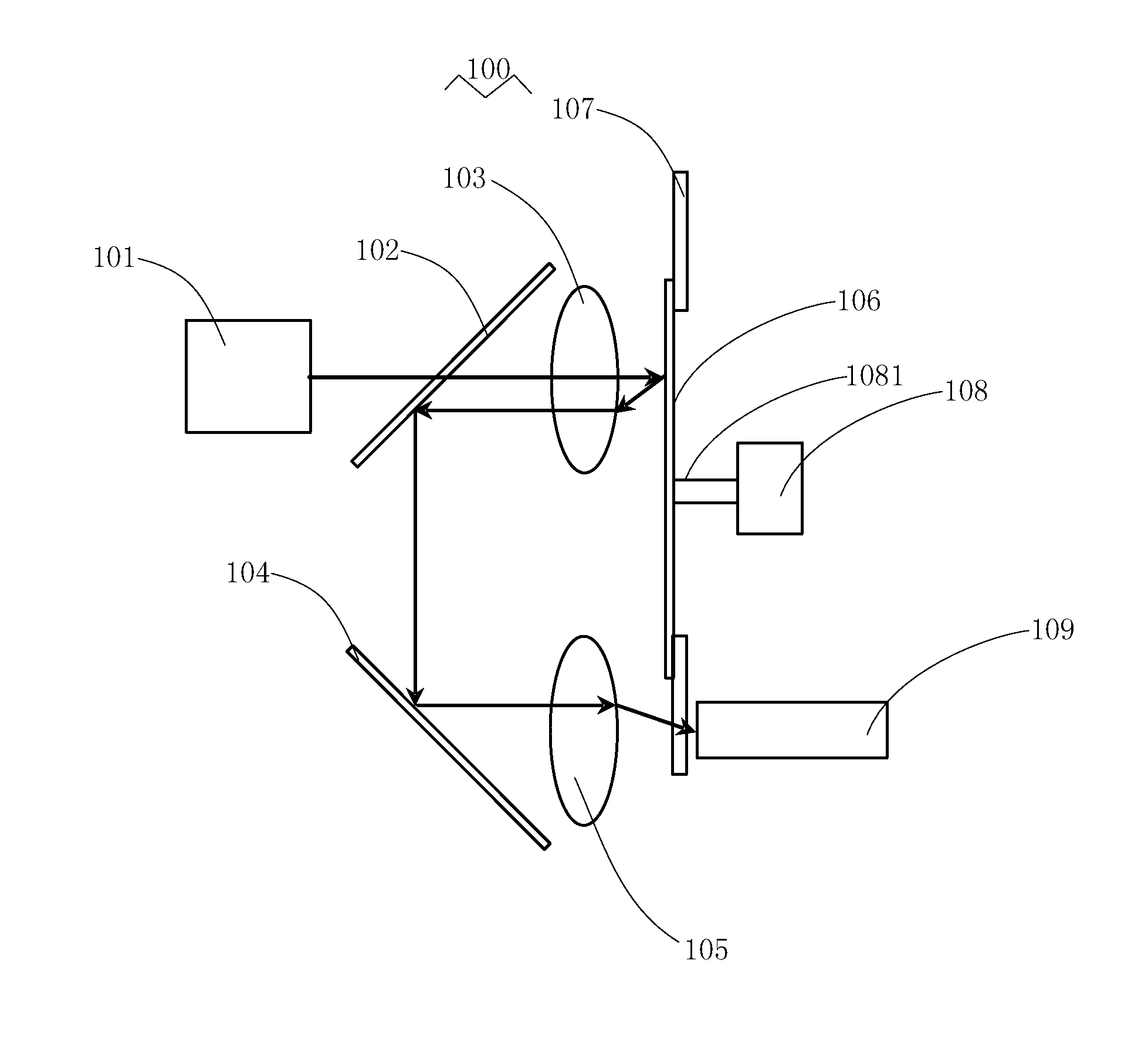
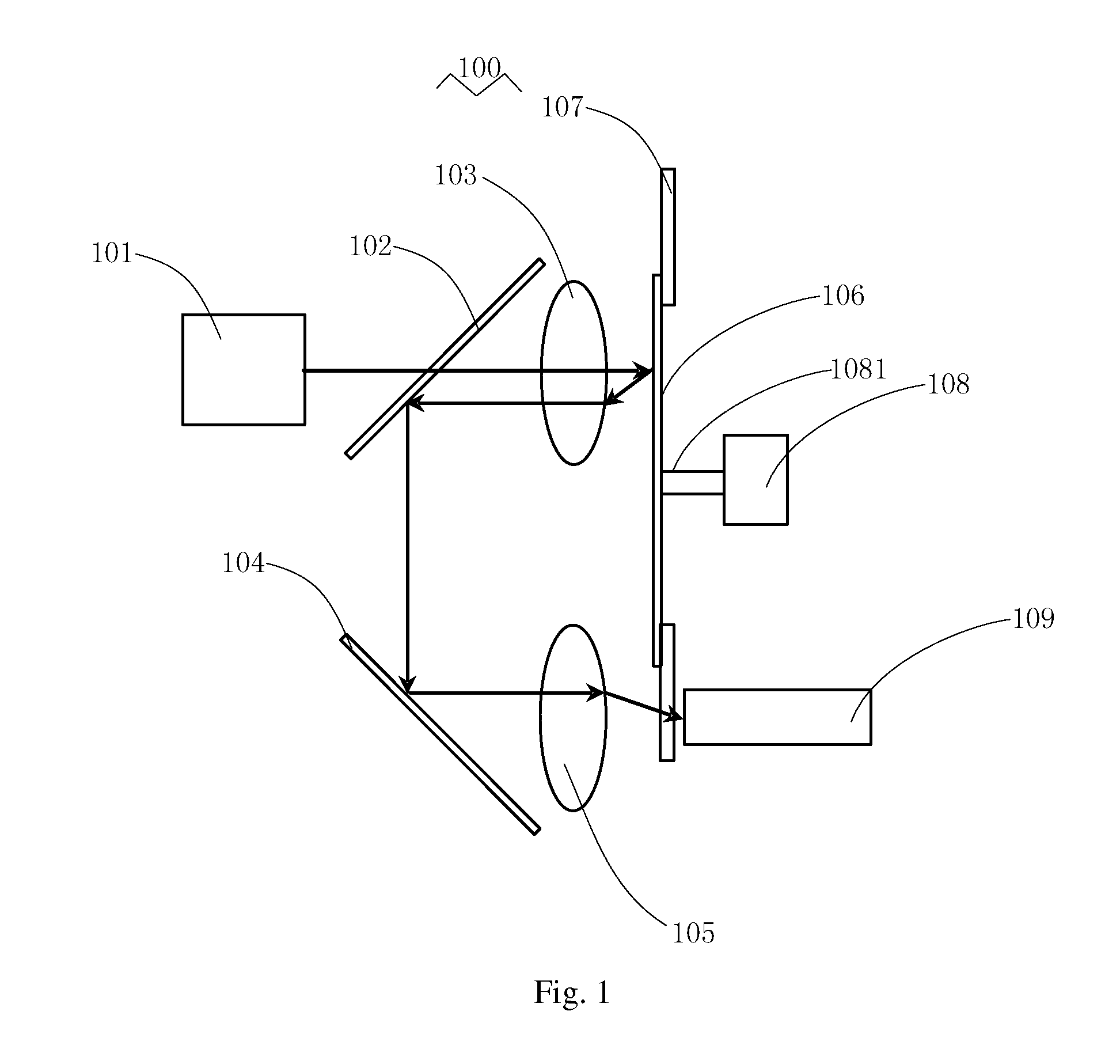
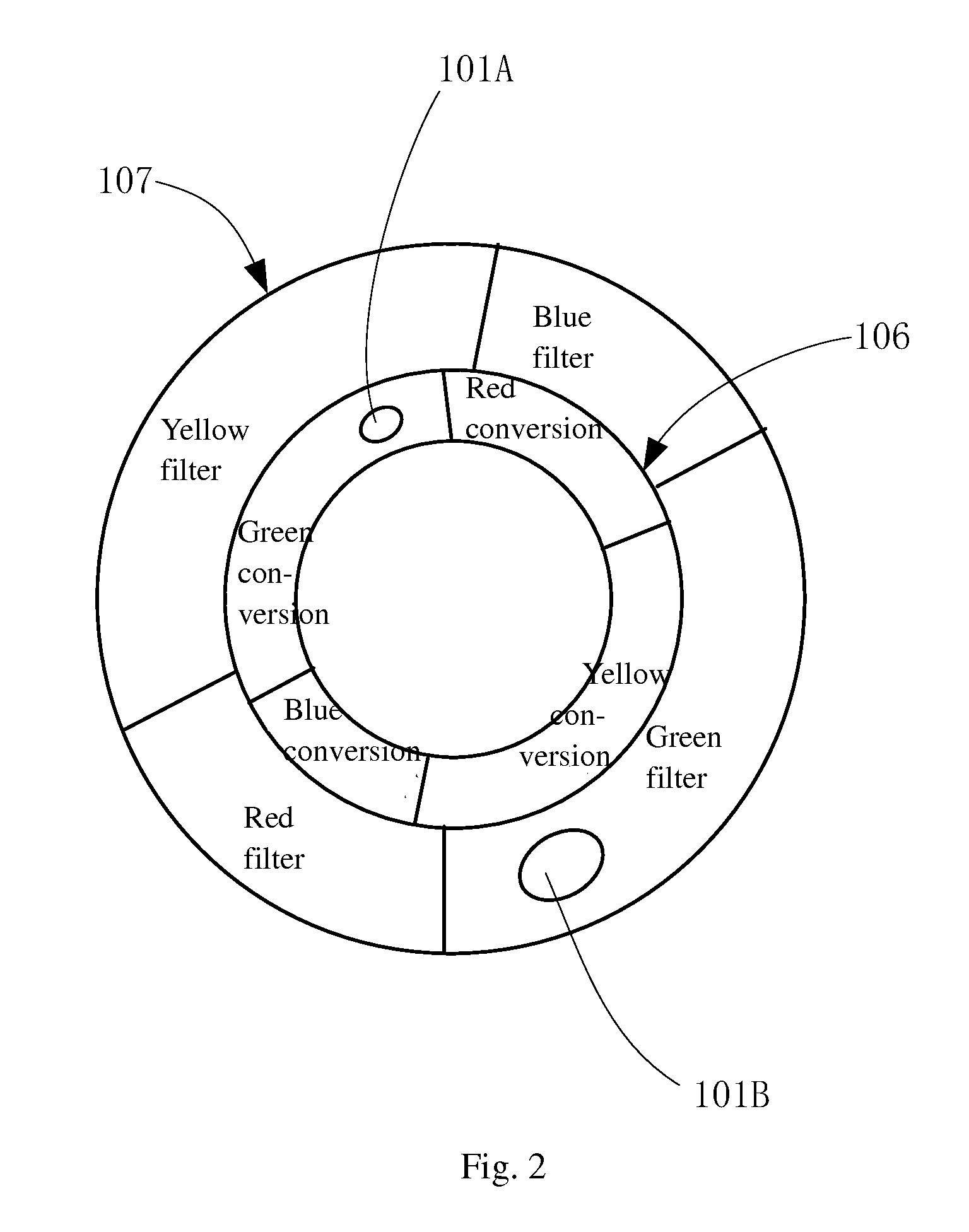
[0051]Referring to FIG. 1 and FIG. 2, FIG. 1 illustrates the structure of a light source system according to the present invention, and FIG. 2 is a front view of the wavelength conversion device and the color filter device in the light source system shown in FIG. 1. As show in FIG. 1, the light source system in this embodiment mainly includes an excitation light source 101, a dichroic mirror 102, a minor 104, lenses 103 and 105, a wavelength conversion device 106, a color filter device 107, a driving device 108 and a light homogenization device 109.

[0052]The excitation light source 101 is for generating an excitation light. In this embodiment, the excitation light source 101 is ultraviolet or near-ultraviolet laser diode or ultraviolet or near-ultraviolet light emitting diode, in order to generate ultraviolet or near-ultraviolet excitation light.

[0053]As show in FIG. 2, the wavelength conversion device 106 has a ring structure, including at least one wavelength conversion area. In t...

second embodiment

[0063]Referring to in FIG. 3 and FIG. 4, FIG. 3 is a schematic structural view of the light source system of the present invention, and FIG. 4 is a front view of the wavelength conversion device and the color filter device of the light source system shown in FIG. 3. The light source system 200 of the present embodiment and the light source system 100 as shown in FIG. 1 and FIG. 2 differ in that: the excitation light source 201 is a blue laser or blue light-emitting diode in order to generate a blue excitation light. As show in FIG. 4, in the present embodiment, besides of a red wavelength conversion area, a yellow wavelength conversion area and a green wavelength conversion area, the wavelength conversion device 206 further includes a blue light transmission area. The color filter device 207 includes a red color filter area, a yellow color filter area and a green color filter area. In the present embodiment, the area of the color filter device 207 which is corresponding to the blue ...

third embodiment

[0066]Referring to FIG. 5 and FIG. 6, FIG. 5 is a schematic structural view of the light source system according to the present invention, FIG. 6 is a front view of the wavelength conversion device and the color filter device of the light source system shown in FIG. 5. The light source system 300 of the present embodiment and the light source system 200 shown in FIG. 3 and FIG. 4 differ in that: the light source 300 further includes. in addition to the excitation light source 301, a red illumination light source 315 (for example, a red laser or a red light emitting diode) in order to generate a red illumination light. The red illumination light source 315 and the excitation light source 301 are respectively provided on the opposite sides of the wavelength conversion device 306 and the color filter device 307. The red illumination light generated by the red illumination light source 315 passes through the lens 314, the dichroic mirror 311, the lens 310 to be incident on the wavelengt...


PUM


Abstract

Provided is a projection system, a light source system, and a light source assembly. The light source system (100) comprises an excitation light source (101), a wavelength conversion device (106), a color filtering device (107), a drive device (108), and a first optical assembly. The wavelength conversion device (106) comprises at least one wavelength conversion region. The optical filtering device (107) is fixed face-to-face with the wavelength conversion device (106), and comprises at least a first optical filtering region. The drive device (108) drives the wavelength conversion device (106) and the optical filtering device (107), allowing the wavelength conversion region and the first optical filtering region to act synchronously, and the wavelength conversion region is periodically set on the propagation path of the excitation light, thereby converting the excitation light wavelength into converted light. The first optical assembly allows the converted light to be incident on the first optical filtering region. The first optical filtering region filters the converted light, so as to enhance the color purity of the converted light. The light source system is simple in structure, easy to implement, and highly synchronous.

Description

FIELD OF THE INVENTION[0001]This invention relates to the field of light source used in illumination and display, and in particular, it relates to projection system, light source system and light source assembly.DESCRIPTION OF THE RELATED ART[0002]Currently, projectors are widely used in various applications, including playing movies, meeting and public events, etc. Phosphor color wheels are often used as the light source of projectors for providing a color light sequence. In such a device, different segments of the phosphor color wheel are alternately and periodically provided in the propagation path of the excitation light, on which the phosphor material coated are excited by the excitation light in order to generate color fluorescent light. However, because the spectral range of the fluorescent light generated by the phosphor material is wide, the color purity of the fluorescent light is poor, which result in an insufficient color gamut of the light source. In this case, color fi...

Claims


Application Information

Patent Timeline
Patent Type & Authority Applications(United States)
IPC IPC(8): F21V9/08F21V9/40
CPCF21V9/08F21V9/16G03B21/204F21Y2101/02F21V13/08F21Y2115/10G02B19/0028G02B19/0047G02B26/008G02F2/006F21S10/007F21K9/64F21Y2115/00G03B21/14G03B21/2066G03B21/28H04N9/3114H04N9/3117H04N9/315H04N9/3155H04N2209/043
Inventor HU, FEILI, YIYANG, YI
Owner APPOTRONICS CORP LTD
Learn More