Active acoustic noise reduction technique

Active Publication Date: 2013-10-03
CHIA YIN HUA
View PDF1 Cites 4 Cited by
  • Summary
  • Abstract
  • Description
  • Claims
  • Application Information

AI Technical Summary

Benefits of technology

[0011]It is a main purpose of this invention to provide for optimal noise reduction capabilities for a variety of noise fields without the use of any feedback technique. The present invention is an active acoustic noise reduction system that comprises sensors at a distance near the source of the noise, which feeds the sampled noise in the electrical media to the main system. In one embod

Problems solved by technology

These passive methods almost always require the installation of heavy, bulky and costly materials such as foams, wools and fibrous bats.
The additional weight bulk and physical change required is in many situations neither practicable nor cost effective.
Also, one of the fundamental problems with insulators or absorbing materials is that they do not work well at reducing noise at the low frequencies.
Furthermore, all existing noise reduction systems utilize the feedback technique in closed environments, which are not ideal for the cancellation of random noise.
Such low frequency disturbances are the common undesired side effect of operating machinery and are difficult to reduce using passive techniques.
This means that active noise reduction systems can be used in many situations where passive methods are impractical due to their bulk, weight and cost effectiveness.
The existing active noise reduction systems still suffer from their own disadvantages, however.
These include the risks associated with system stability, less than adequate noise suppression performance and insufficient operati

Method used


Image

  • Active acoustic noise reduction technique
  • Active acoustic noise reduction technique
  • Active acoustic noise reduction technique

Examples


Embodiment Construction

[0018]Some embodiments of the present invention are described in detail with reference to the related drawings of FIGS. 1 through 5. Additional embodiments, features and / or advantages of the invention will become apparent from the ensuing description or may be learned by practicing the invention.

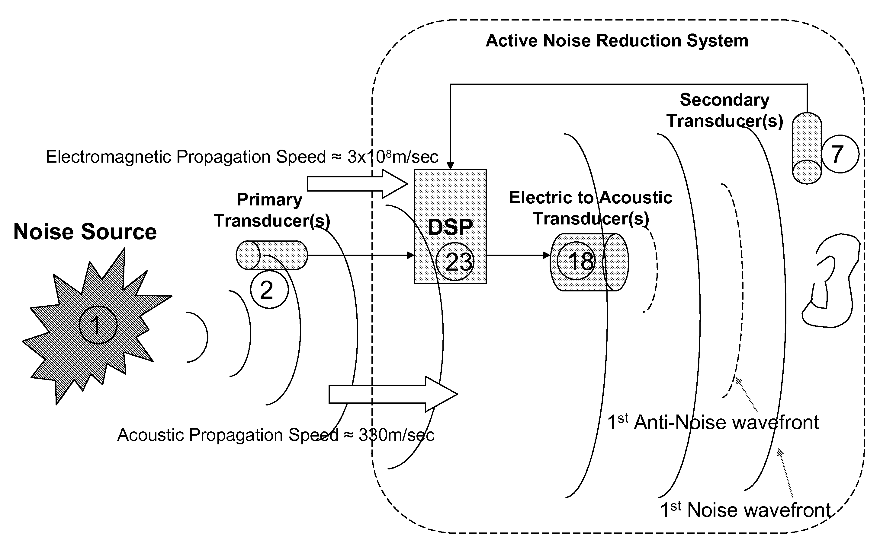
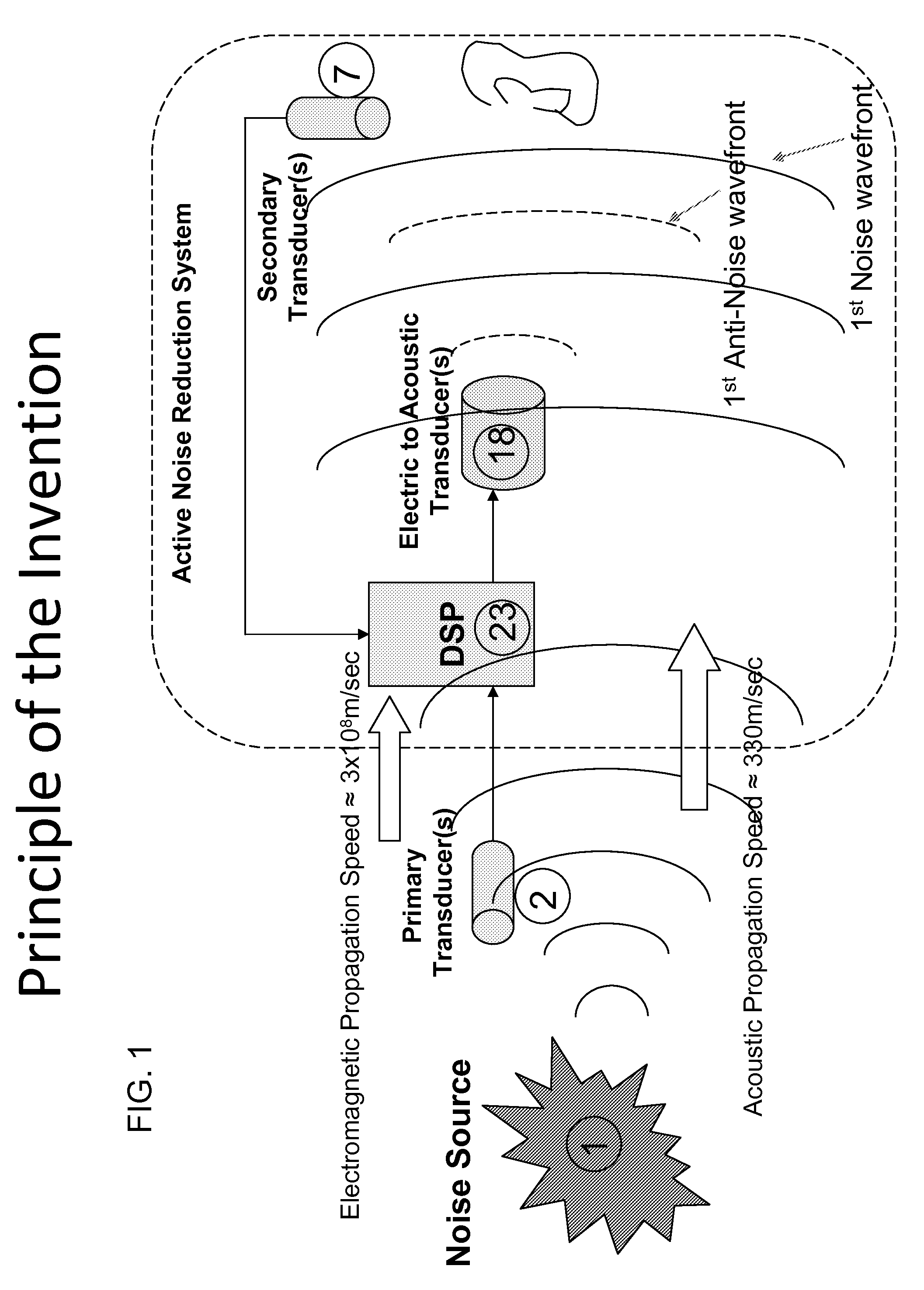
[0019]FIG. 1 generally shows one embodiment of the active noise reduction system. A noise source 1 at the beginning of the diagram is sensed by the primary transducer 2, which then feeds the sampled noise through either wired or wireless means into a digital signal processor (DSP) within the main system. The DSP 23 then feeds into an electric to acoustic transducer 18. The acoustic propagation speed of the noise is approximately 340 m / sec while the electromagnetic propagation speed of the noise is approximately 3×10̂8 m / sec. The system takes advantage of the received electrical noise signal a delta time ahead of the arrival acoustic noise, thus generating a process to cancel the noise with o...


PUM


Abstract

An acoustical noise reduction system which comprises a primary acoustic to electric transducer, digital signal processor (DSP), an electric to acoustic transducer, and a secondary acoustic to electric transducer is disclosed in the present invention. The active noise reduction system is located close to the noise source with the sound being sensed by a primary transducer before the noise enters the active noise reduction area. The system functions to generate an anti-noise cancellation sound wave with an acoustic propagation speed of approximately 330 m/sec and an electromagnetic propagation speed of approximately 3×10̂8 m/sec.

Description

FIELD OF THE INVENTION[0001]This invention relates to active acoustical noise reduction systems.BACKGROUND OF THE INVENTION[0002]Formulating practical solutions for the reduction of problematic noise is an active area of engineering research in both the fields of acoustics and control. To date, noise reduction has been mostly carried out using passive means. These passive methods almost always require the installation of heavy, bulky and costly materials such as foams, wools and fibrous bats. The additional weight bulk and physical change required is in many situations neither practicable nor cost effective. Also, one of the fundamental problems with insulators or absorbing materials is that they do not work well at reducing noise at the low frequencies. This is primarily because the acoustic wavelength at low frequencies becomes large compared to the thickness of typical absorbent materials. Furthermore, all existing noise reduction systems utilize the feedback technique in closed ...

Claims


Application Information

Patent Timeline
IPC IPC(8): G10K11/16
CPCG10K11/1784G10K11/17823G10K11/17825G10K11/17853G10K11/17881
Inventor CHIA, YIN-HUA
Owner CHIA YIN HUA
Why Eureka
Try Eureka