Method of making a medical balloon

a balloon and balloon body technology, applied in the field of balloon making, can solve the problems of complex and time-consuming, difficult process, and inability to properly dilate hardened and/or calcified regions, and achieve the effect of minimizing shrinkage and maximizing burst strength

Active Publication Date: 2013-10-03
COOK MEDICAL TECH LLC
View PDF6 Cites 33 Cited by
  • Summary
  • Abstract
  • Description
  • Claims
  • Application Information

AI Technical Summary

Benefits of technology

[0022]Where the heat set temperature is a temperature range, the first layer may have an optimum heat set temperature within the heat set temperature range. Heating the balloon to the optimum heat set temperature of the first layer may result in a balloon for which shrinkage is minimized and burst strength is maximized.
[0023]Due to the relative hardness of the two layers, the first layer may provide a harder support for the second layer.

Problems solved by technology

In angioplasty techniques the proper dilation of stenosed regions that are hardened and / or have become calcified can be difficult with a standard medical balloon.
The blades may be fixed to the balloon with a layer of adhesive in a process can be fiddly and time consuming.
Often the manufacture of medical balloons is a complex and time consuming task, particularly having regard to the importance for reliability of the device.

Method used


Image

  • Method of making a medical balloon
  • Method of making a medical balloon
  • Method of making a medical balloon

Examples


Embodiment Construction

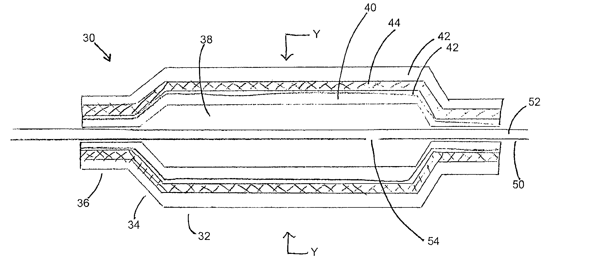
[0044]It is to be understood that the drawings are schematic only and are not intended to be representative of dimensions or proportions of the various elements shown therein. In some instances, dimensions, sizes and proportions have been modified in order to assist in the visualization of various features of the elements shown, that is for the purpose of explanation only. The person skilled in the art will be aware of the appropriate dimensions and proportions having regard to common knowledge in the art.

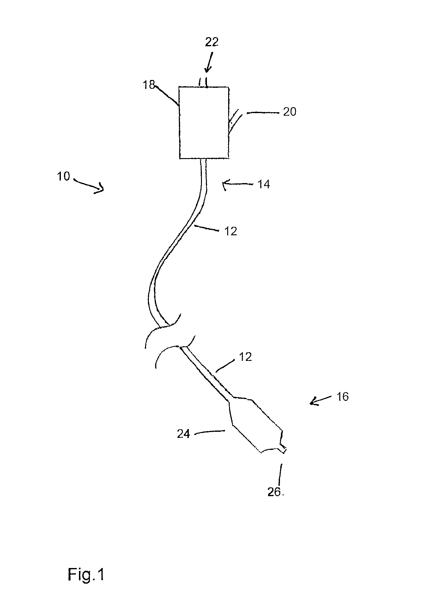
[0045]Referring to FIG. 1, there is shown in schematic form the principal components of a balloon catheter assembly 10, which components are generally known in the art. The balloon catheter includes a catheter 12 having a proximal end 14 and a distal end 16. At the proximal end 14, the catheter is coupled to a manipulation unit and valve assembly 18, which typically includes one or more haemostatic valves (not shown), a port 20 for feeding flushing liquid into the catheter 12, typi...


PUM

PropertyMeasurementUnit
temperatureaaaaaaaaaa
melting temperatureaaaaaaaaaa
temperatureaaaaaaaaaa

Abstract

A medical balloon for a balloon catheter is described. The balloon has at least a first layer made from a first material and a second layer made from a second material, said first and second layers being in overlying relationship with one another and being integral with one another; wherein the first layer has a softening or melting temperature which is higher than a softening or melting temperature of the second layer. A method of forming the medical balloon is also described, including locating a raw tubing in a mold; preheating and inflating the raw tubing so as to cause it to stretch; heating the raw tubing to soften or melt the second layer; setting the inflated raw tubing to form the medical balloon; and cooling the set balloon.

Description

CROSS-REFERENCE RELATED APPLICATIONS[0001]This application claims priority to GB application no. 1205369.0, filed Mar. 27, 2012, titled “Method of Making a Medical Balloon,” the contents of which are incorporated herein by reference.TECHNICAL FIELD[0002]The present invention relates to a method of making a medical balloon, to a medical balloon and to a balloon catheter including such a balloon.BACKGROUND ART[0003]Medical balloons are used for a variety of medical procedures including angioplasty, scoring, vessel dilatation, valvuloplasty, occlusion and for many other applications. In many such applications, it is desirable to provide additional components to tailor the balloon to improve its function in each of the various specific uses. One common procedure involving the use of a balloon catheter relates to angioplasty dilation of coronary or other arteries suffering from stenosis (that is, a narrowing of the arterial lumen which restricts blood flow). In angioplasty techniques the...

Claims


Application Information

Patent Timeline
Patent Type & Authority Applications(United States)
IPC IPC(8): A61M25/10
CPCB29L2031/7543B29C49/04B29C49/22A61M2025/1075A61M25/104A61M25/1029A61L29/18B29C49/786A61L29/041A61L29/049A61L29/06
Inventor AGGERHOLM, STEENBODEWADT, TUE THURENLYSGAARD, THOMAS
Owner COOK MEDICAL TECH LLC
Why Eureka
Try Eureka