Power distribution system and method

a power distribution system and power distribution technology, applied in the field of power distribution system and method, can solve the problems of consumers not being able to control their devices from anywhere, consumers not being able to easily access devices at home and away from home, and existing internet based home automation devices suffering

Active Publication Date: 2013-10-03
ADVANERGY
View PDF0 Cites 284 Cited by
  • Summary
  • Abstract
  • Description
  • Claims
  • Application Information

AI Technical Summary

Benefits of technology

[0044]The present invention in various embodiments addresses one or more of the above objectives in the following manner. The present invention as generally depicted in FIG. 1 (0100) implements a Smart Gateway Power Controller (SGPC) (0110) that acts as a bridge between a power source (0101) and associated power source cabling (0102) and power load cabling (0103) to supply power to one or more electrical loads (0104). The SGPC (0110) incorporates a power switch (0111) and power / energy meter (0112) that are interfaced to a microcontroller unit (MCU) (0113) or other computing device operating under control of software read from a computer readable medium (0114). The MCU (0113) interfaces with one or more WiFi wireless network interface modules (0115, 0116) which communicate to one or more computer networks that may include the Internet, local computer networks, and / or other networks such as ZIGBEE®, etc.
[0045]A typical application context for the present invention is generally illustrated in FIG. 2 (0200), wherein a user (0201) interfaces with a graphical user interface (GUI) (0210) that may be embodied on any number of devices including but not limited to a mobile phone (0211), laptop / desktop computer (0212), and / or tablet computer (0213). This GUI typically operates under control of software read from a computer readable medium (0202) that incorporates network protocols that communicate over a computer network (0203) (such as the Internet) to a local wireless router (0204). This wireless router (0204) then communicates with one or more SGPC devices (0221, 0222, 0223) to control power switching to any number of load devices (0231, 0232, 0233, 0234) using any number of SGPC associated power receptacles.

Problems solved by technology

Consumers cannot control them from anywhere.
Existing Internet based home automation devices, however, suffer the following drawbacks:Consumers cannot easily access the devices both at home and away from home.Consumers have to log on to a service provider's website while away from home, and from there read the data and control the automation device.
Consumers cannot communicate with the device directly.
This presents some security issues as well as performance issues.This type of device is usually intrusive to existing home network as consumers either need to get a new home gateway to work with the automation device or add a new router or hub to the home network to “relay” the signals.
The challenges these systems encounter in their home deployment are:Service Provider Centric vs.
There are privacy issues and the issues of consumer's ability to access the data.
Deployed automation and energy management systems of today require the consumer to remotely login to a service provider site for information and provides no method for easy and direct access to or control over the device.Network Issues—When an automation device is deployed at home, it either has to work with existing home residential gateway (the AP) or replace the existing home gateway with a new home gateway that knows how to communicate with the automation device.
This “intrusive” setup that often requires professional setup forces consumers to make changes in their home network setup.
In addition, once the energy management network is deployed at a home, it is not easy to deploy additional energy management devices from other vendors.Performance—As mentioned above, many existing home energy systems do not allow consumers to access or control them DIRECTLY via a smartphone or a tablet, even if the user is proximal to the energy system.
As a result, it introduces delays, sometimes significant delays, depending on the overall network traffic.
The prior art as detailed above suffers from the following deficiencies:Prior art power distribution systems generally do not permit integration of disparate types of home automation networks.Prior art power distribution systems generally do not interface well with the Internet and rely on proprietary interface protocols operating within a locally defined network interface to affect power distribution functions.Prior art power distribution systems generally do not permit “nesting” or “subnetting” of control networks to define hierarchical control domains that can be accessed remotely via the Internet or some other network interface.
While some of the prior art may teach some solutions to several of these problems, the core issue of integrating disparate home automation networks with Internet based communication control systems has not been solved by the prior art.

Method used


Image

  • Power distribution system and method
  • Power distribution system and method
  • Power distribution system and method

Examples


embodiment

Preferred Embodiment Method Summary

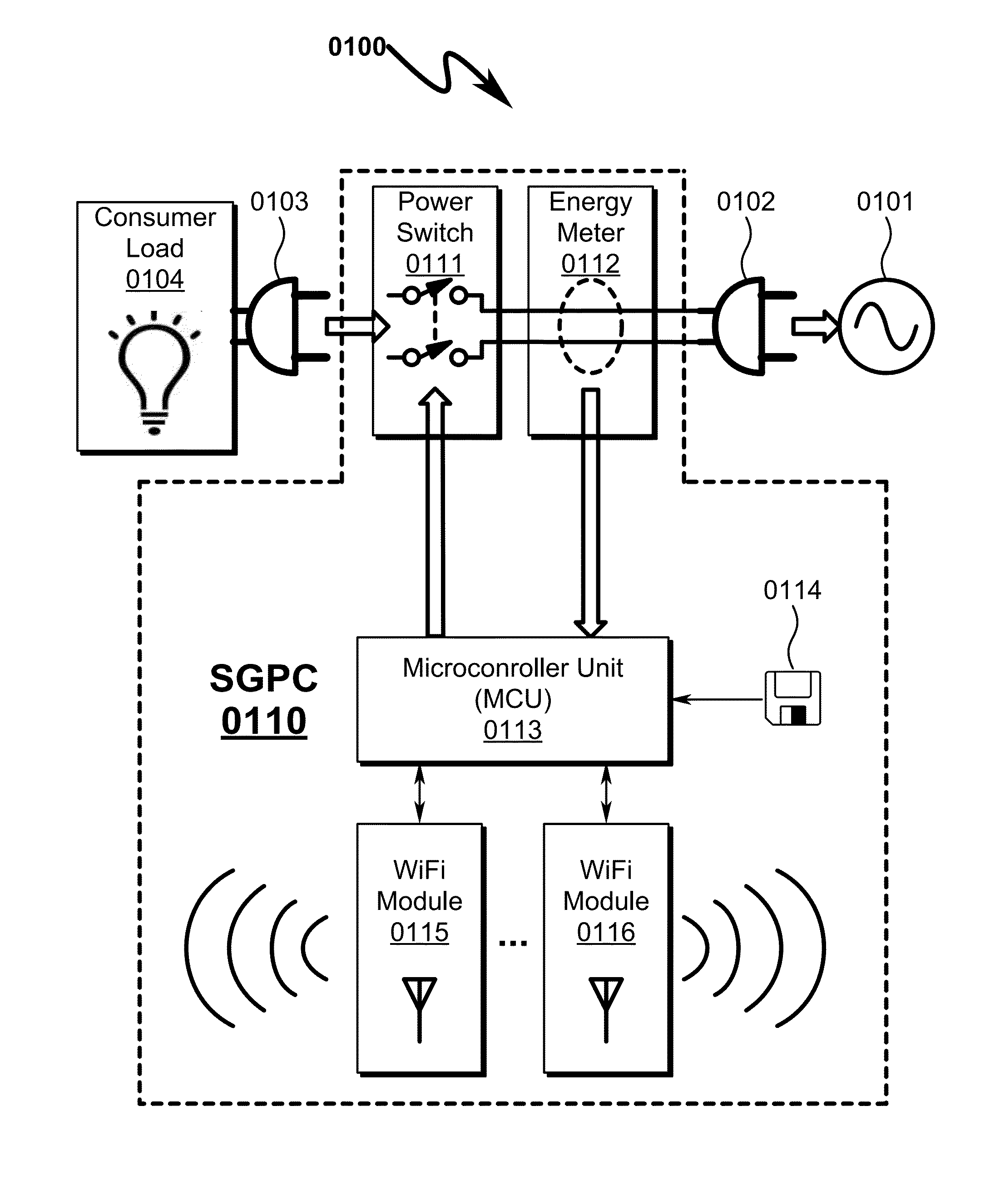
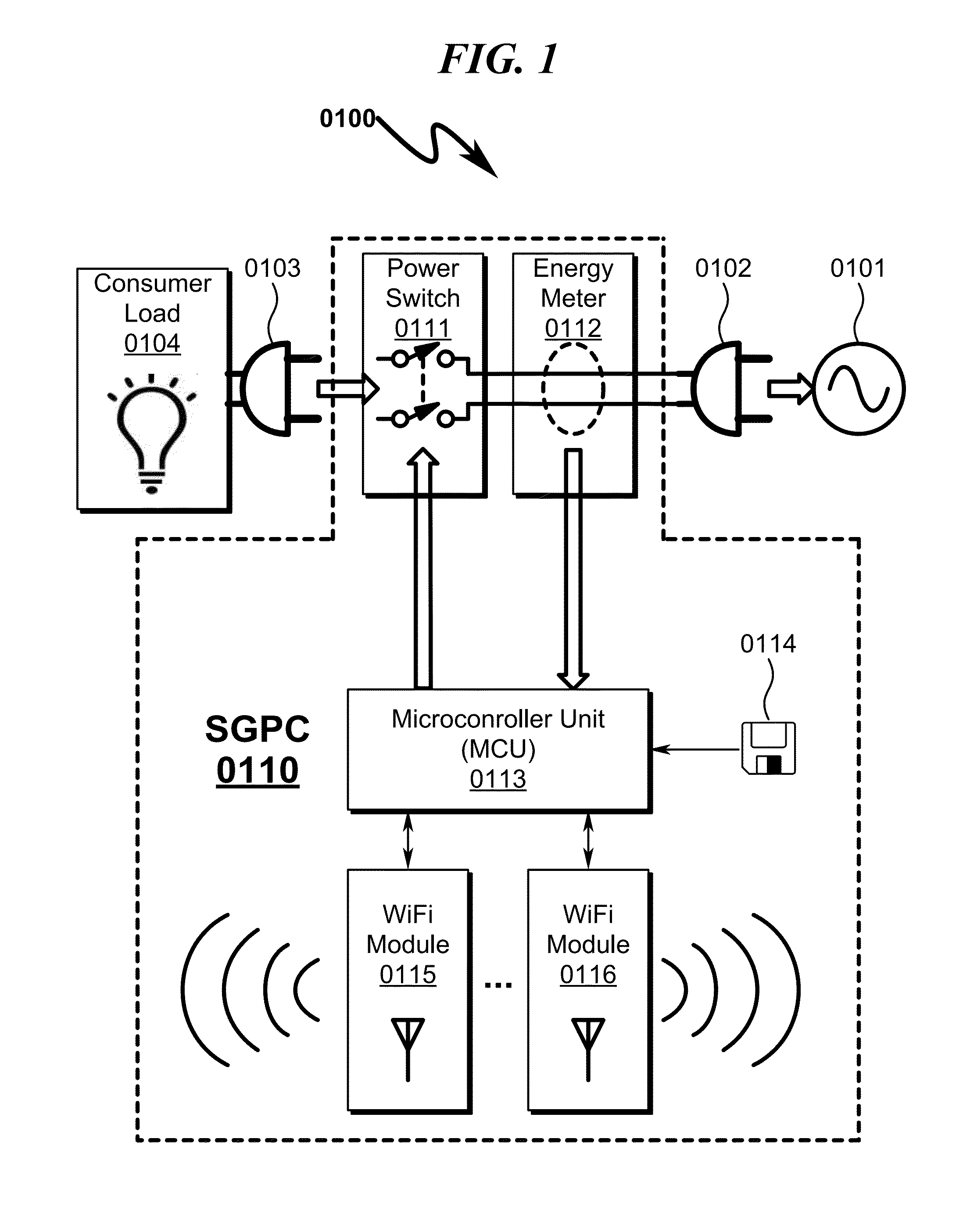
[0561]The present invention preferred exemplary method embodiment anticipates a wide variety of variations in the basic theme of implementation, but can be generalized as a power distribution method, the method operating in conjunction with a SGPC power distribution system comprising:

[0562](a) power load receptacle;

[0563](b) power switch;

[0564](c) power monitor;

[0565](d) computing device; and

[0566](e) wireless communication interface;

[0567]wherein[0568]the SGPC is configured to be enclosed within a rectangular cuboid enclosure;[0569]the power switch comprises a primary and secondary contactor, the primary and secondary contactor electrically connected in response to a control input;[0570]the primary contactor of the power switch is electrically connected to a power source;[0571]the power load receptacle is electrically connected to the secondary contactor of the power switch;[0572]the power monitor produces a power value output in response to the e...


PUM


Abstract

A power distribution system/method implementing Internet based access to hybrid home automation networks is disclosed. The system utilizes a smart gateway power controller (SGPC) configured for single/multi-gang wallplate installation to selectively switch an AC power source to a load device under switched control and/or local/remote network commands that may be routed through a variety of network interfaces and protocols present within a home or other structure-local communications network. SGPC configurations may be nested within a home automation network to permit separation of control for load devices within a common home automation environment. Present invention methods may include routing protocols between disparate home automation networks as well as remote access protocols that permit control of disparate home automation networks via the Internet using a wide variety of remote access interfaces including mobile devices, tablet computers, laptops, desktop computers, and the like.

Description

CROSS REFERENCE TO RELATED APPLICATIONSU.S. Utility Patent Application[0001]This application is a Continuation-In-Part and incorporates by reference United States Utility Patent Application for POWER CONTROL SYSTEM AND METHOD by inventors Jin (nmn) Lu, Todd Scott Kelly, and Lee (nmn) Cheung, filed electronically with the USPTO on Oct. 4, 2012, with Ser. No. 13 / 644,795, EFS ID 13909359, confirmation number 6416, docket AADVN.0101. This parent application will be referred to as “Document PCSM.”PCT Patent Applications[0002]This application claims benefit under 35 U.S.C. §120 and incorporates by reference PCT Patent Application for POWER CONTROL SYSTEM AND METHOD by inventors Jin (nmn) Lu, Todd Scott Kelly, and Lee (nmn) Cheung, filed electronically with the USPTO on Oct. 4, 2012, with serial number PCT / US2012 / 058761, EFS ID 13913022, confirmation number 4896, docket AADVN.0101PCT.U.S. Provisional Patent Applications[0003]U.S. patent application Ser. No. 13 / 644,795 filed Oct. 4, 2012 cl...

Claims


Application Information

Patent Timeline
Patent Type & Authority Applications(United States)
IPC IPC(8): G05B13/02
CPCH04L12/2807H04L12/2836H04L12/66G05B13/02Y02B70/325H04L61/2514H04L12/2825H04L2012/2841G08C17/02G08C2201/93H04L61/3065Y04S20/228H04L2101/365Y02B70/30Y04S20/20
Inventor LU, JINKELLY, TODD SCOTTCHEUNG, LEE
Owner ADVANERGY
Why Eureka
Try Eureka