Method of making a semiconductor radiation detector

a radiation detector and semiconductor technology, applied in the field can solve the problems of excessive side surface leakage current and/or noise generation, difficulty in properly controlling side wall properties, and limited fabrication of detectors with side wall extended electrodes (e.g., semi-hemispherical detectors), and achieve the effect of improving the art of semiconductor radiation detectors

a radiation detector and semiconductor technology, applied in the field can solve the problems of excessive side surface leakage current and/or noise generation, difficulty in properly controlling side wall properties, and limited fabrication of detectors with side wall extended electrodes (e.g., semi-hemispherical detectors), and achieve the effect of improving the art of semiconductor radiation detectors

US20130264669A1Active Publication Date: 2013-10-10PRODUCE

Image

  • Method of making a semiconductor radiation detector
  • Method of making a semiconductor radiation detector
  • Method of making a semiconductor radiation detector

Examples


Embodiment Construction

[0025]For a better understanding of the present invention, together with other and further objects, advantages and capabilities thereof, reference is made to the following disclosure and appended claims in connection with the above-described drawings. It is understood that like numerals will be used to indicate like elements from drawing figure to drawing figure.

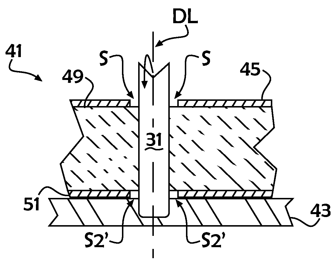
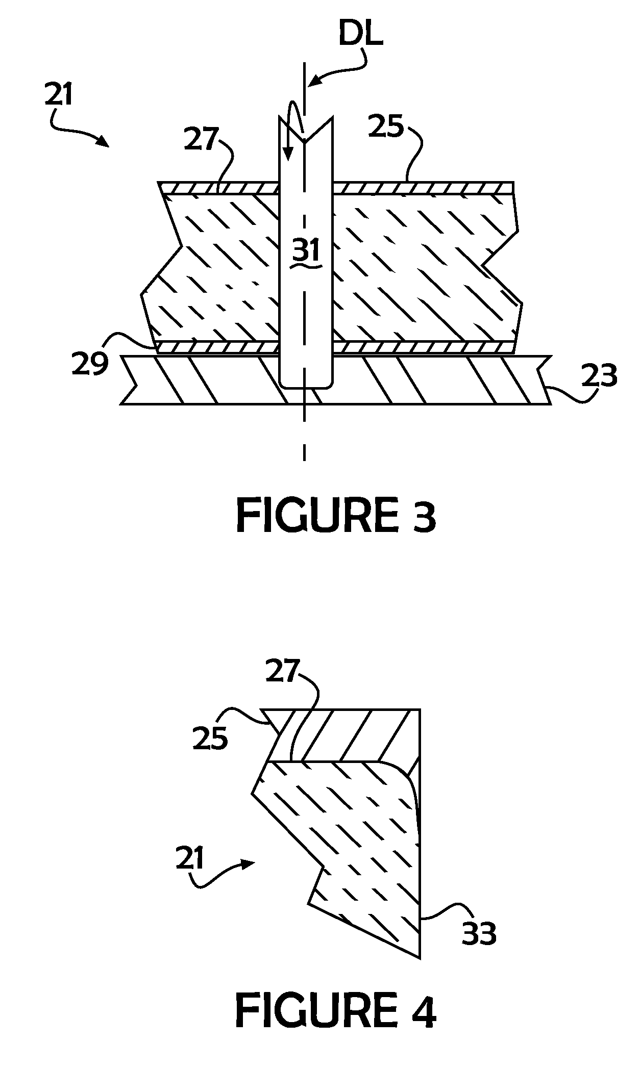
[0026]As understood from the description herein, the present invention provides a new and unique design and fabrication process to limit the potential adverse effects of post-diced side surfaces on final detector performance. The basic concept involves the recession of at least one electrode metallization layer from the semiconductor dice line to prevent direct physical contact between the dicing blade and metal. Formation of the metal layer(s) may be accomplished by slightly modified conventional means including, e.g., shadow masking (e.g., where sputtering occurs through a metal, e.g., nickel, mask), photolithographic proc...


PUM


Abstract

A method of making a semiconductor radiation detector wherein the metal layers which serve as the cathode and anode electrodes are recessed from the designated prospective dice lines which define the total upper and lower surface areas for each detector such that the dicing blade will not directly engage the metal during dicing and therefore prevent metal from intruding upon (smearing) the vertical side walls of the detector substrate.

Description

FIELD OF THE INVENTION[0001]The invention relates to semiconductor radiation detectors and, more particularly, to a new and improved semiconductor radiation detector having enhanced radiation detection capabilities. The invention even more particularly relates to the method of making such an enhanced detector.BACKGROUND OF THE INVENTION[0002]Presently known semiconductor radiation detectors, particularly those designed for the detection of gamma and x-ray photons and charged particles and typically utilized in instruments for radiation spectroscopy, medical imaging, etc., are usually of a configuration in which the bulk-detecting crystals (e.g., cadmium telluride (CdTe) and cadmium zinc telluride (CdZnTe) crystals) which form the semiconductor plate or substrate are sandwiched between spaced-apart cathode and anode electrodes. Very often, the detector is of planar configuration with opposing planar surfaces and adjacent planar side walls perpendicular to the metalized surfaces. The ...

Claims


Application Information

Patent Timeline
10 Oct 2013
Publication
US20130264669A1
IPC
H01L27/14; H01L31/18
CPC
H01L31/022408; H01L27/14676; Y02E10/543; H01L31/085; H01L31/1828; H01L27/14696
Inventors
LI, HANDONG; PROKESCH, MICHAEL