Film Cooling Performance Optimization for Enhanced High Pressure Turbine Durability

a technology of high-pressure turbines and optimization of film cooling, which is applied in the direction of design optimization/simulation, instruments, cad techniques, etc., can solve the problems of not fully developed or available whole film cooling arrays in the process, the effect of optimizing film cooling performance and achieving higher fitness function values

Active Publication Date: 2013-10-10
THE UNITED STATES OF AMERICA AS REPRESETNED BY THE SEC OF THE AIR FORCE
View PDF9 Cites 26 Cited by
  • Summary
  • Abstract
  • Description
  • Claims
  • Application Information

AI Technical Summary

Benefits of technology

[0009]A method, apparatus and program product are provided to optimize film cooling performance for turbomachinery components. Embodiments of the invention define a design space by selecting process variables and limits. The embodiments provide a random initial population of a plurality of designs using Latin hypersquare sampling, varying the process variables across the design space. Each design of the plurality of designs is evaluated. Fitness function values are determined based on a performance of each of the evaluated designs of the plurality of designs. Half of the plurality of designs having higher fitness function values is selected. The embodiments of the invention randomly pair designs of the selected half of the plurality of designs to generate two new designs from each random pair of designs forming a plurality of new designs.

Problems solved by technology

Thus, cooling may be applied to high temperature components at a penalty to the efficiency of the engine.
But even with these advances reliable simulation tools, physical models, and all-encompassing turbomachine design methods that consider individual 3-D geometries, pertinent flow conditions, and whole film cooling arrays in the process are not fully developed or available.
Currently, design practices related to film cooling configurations involve a high amount of empiricism and may be missing important physical behaviors that have direct impacts on durability, especially for the hottest part that sees the harshest environment, the HPT.
This prohibits accurate knowledge of thermally-driven stresses for a specific part given its unique geometry.
Unfortunately, due to the intense compute power required, CFD codes are typically not used in the process of film cooling design.
While industry has taken advantage of contemporary computing power to design for optimal aerodynamic shapes and structural design, the same cannot be said for film cooling design.

Method used


Image

  • Film Cooling Performance Optimization for Enhanced High Pressure Turbine Durability
  • Film Cooling Performance Optimization for Enhanced High Pressure Turbine Durability
  • Film Cooling Performance Optimization for Enhanced High Pressure Turbine Durability

Examples


Embodiment Construction

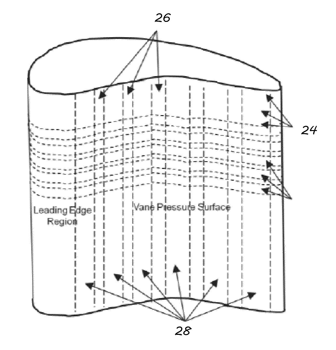
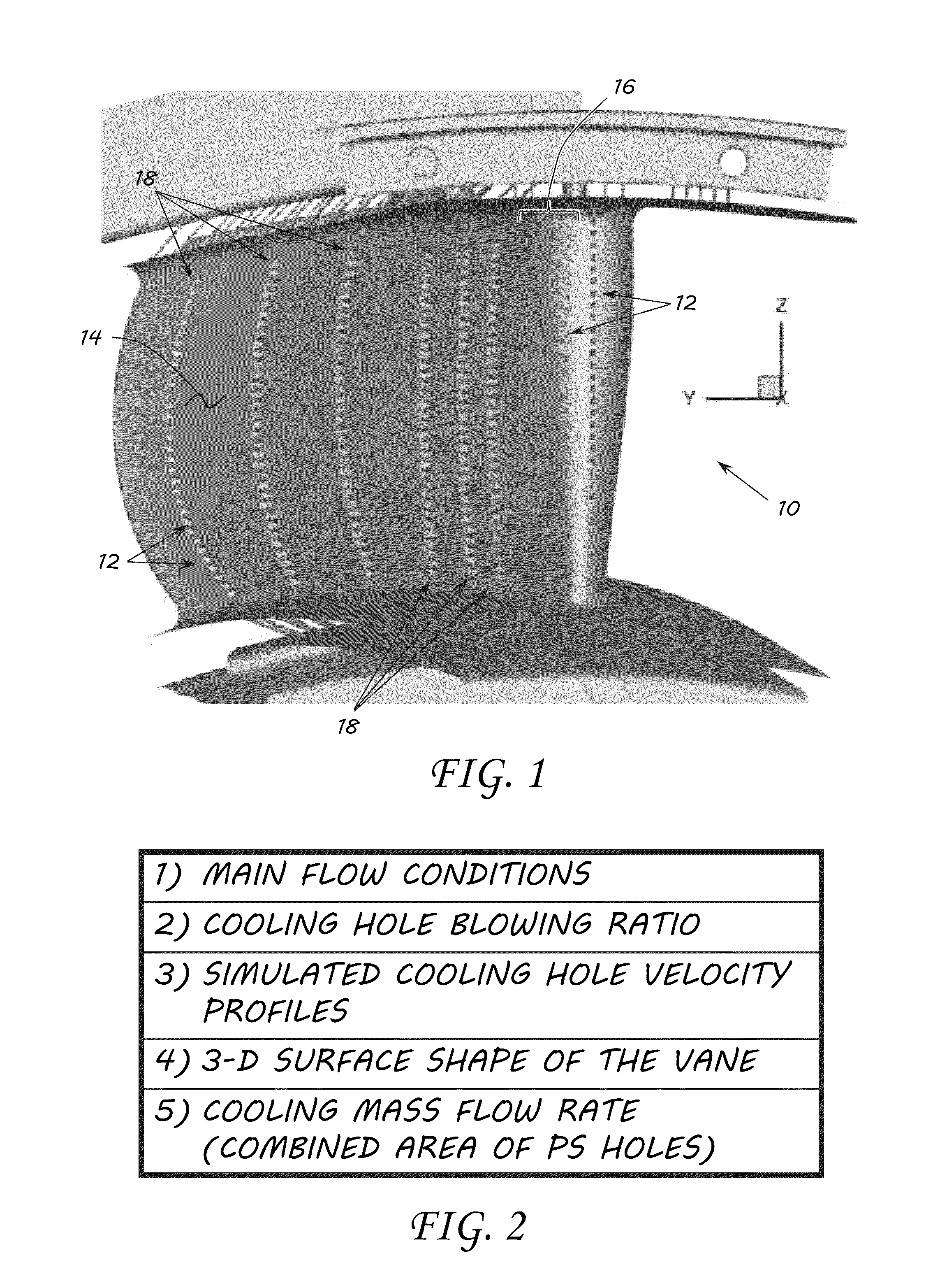
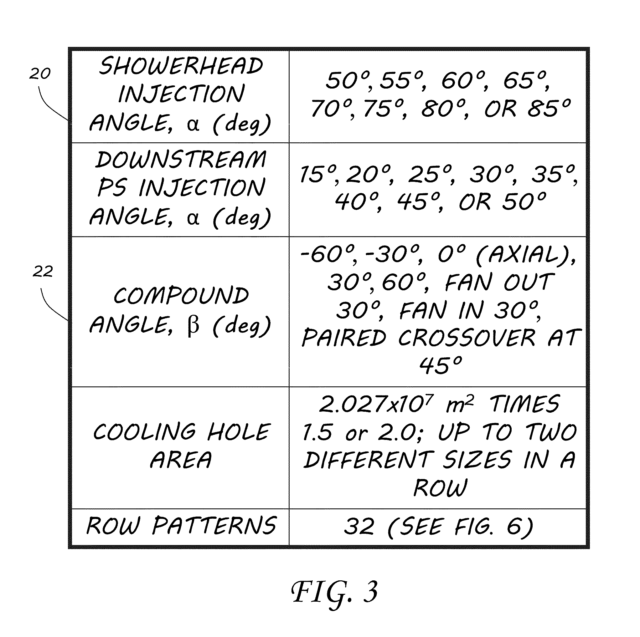
[0039]Contemporary high pressure turbine (HPT) durability design methods in industry generally utilize dated correlations and spreadsheet methods based on “rules of thumb”. Of the over 2,700 film cooling references in existence, no known efforts have been made towards an optimized overall film cooling design for a realistic HPT vane geometry in proper flow conditions. Nor has there been a major attempt in open literature to improve component cooling design methods in general. This work invests greater effort in the design and optimization of a HPT vane film cooling array by way of considering numerous configurations, variables, and variable value ranges within a design space. Cooling hole surface location, size, injection orientation, and row patterns may be varied in the design space. In some embodiments of the invention, the design space may be optimized by way of Latin hypercube sampling (LHS) and multi-objective genetic algorithms (GAs) to maximize cooling effectiveness and mini...


PUM


Abstract

A method, apparatus and program product are provided to optimize film cooling performance for turbomachinery components. A design space is defined by selecting process variables and limits. A random initial population of a plurality of designs is provided using Latin hypersquare sampling, varying the process variables across the design space. Each design of the plurality of designs is evaluated. A fitness function value is determined based on a performance of each of the evaluated designs of the plurality of designs. A half of the plurality of designs having higher fitness function values is selected. Designs of the selected half of the plurality of designs are randomly paired to generate two new designs from each random pair of designs forming a plurality of new designs.

Description

RIGHTS OF THE GOVERNMENT[0001]The invention described herein may be manufactured and used by or for the Government of the United States for all governmental purposes without the payment of any royalty.BACKGROUND OF THE INVENTION[0002]1. Field of the Invention[0003]The present invention generally relates to gas turbine engines and, more particularly, optimization of film cooling configurations therefor.[0004]2. Description of the Related Art[0005]Gas turbines, also called combustion turbines, are a type of internal combustion engine. They have an upstream rotating compressor coupled to a downstream turbine, and a combustion chamber in-between. Energy is added to a gas stream in the combustor, where fuel is mixed with air and ignited. In the high pressure environment of the combustor, combustion of the fuel increases the temperature. The products of the combustion are forced into the turbine section. There, the high velocity and volume of the gas flow is directed through a nozzle over...

Claims


Application Information

Patent Timeline
Patent Type & Authority Applications(United States)
IPC IPC(8): G06F17/50G06F7/60
CPCG06F17/5018G06F2217/16G06F17/5086G06F2111/10G06F30/17G06F30/23G06F30/28G06F2113/08
Inventor CLARK, JOHN PAULJOHNSON, JAMIE JAYOOTEN, MICHAEL KENNETH
Owner THE UNITED STATES OF AMERICA AS REPRESETNED BY THE SEC OF THE AIR FORCE
Why Eureka
Try Eureka