Microwave plasma torch generating laminar flow for materials processing

Active Publication Date: 2013-10-17
6K INC
View PDF87 Cites 52 Cited by
  • Summary
  • Abstract
  • Description
  • Claims
  • Application Information

AI Technical Summary

Benefits of technology

[0011]Therefore, an object of the present invention is to provide a laminar flow environment, free of turbulent flow effects, for the material that goes through the plasma resulting in nanoparticles with uniform sizes and shapes and a homogenous materials distribution.
[0012]It is another object of the present invention to enhance plasma pro

Problems solved by technology

This subjects the materials to significantly asymmetrical temperature profiles and results in non-uniform particles and non-ho

Method used


Image

  • Microwave plasma torch generating laminar flow for materials processing
  • Microwave plasma torch generating laminar flow for materials processing
  • Microwave plasma torch generating laminar flow for materials processing

Examples


Example

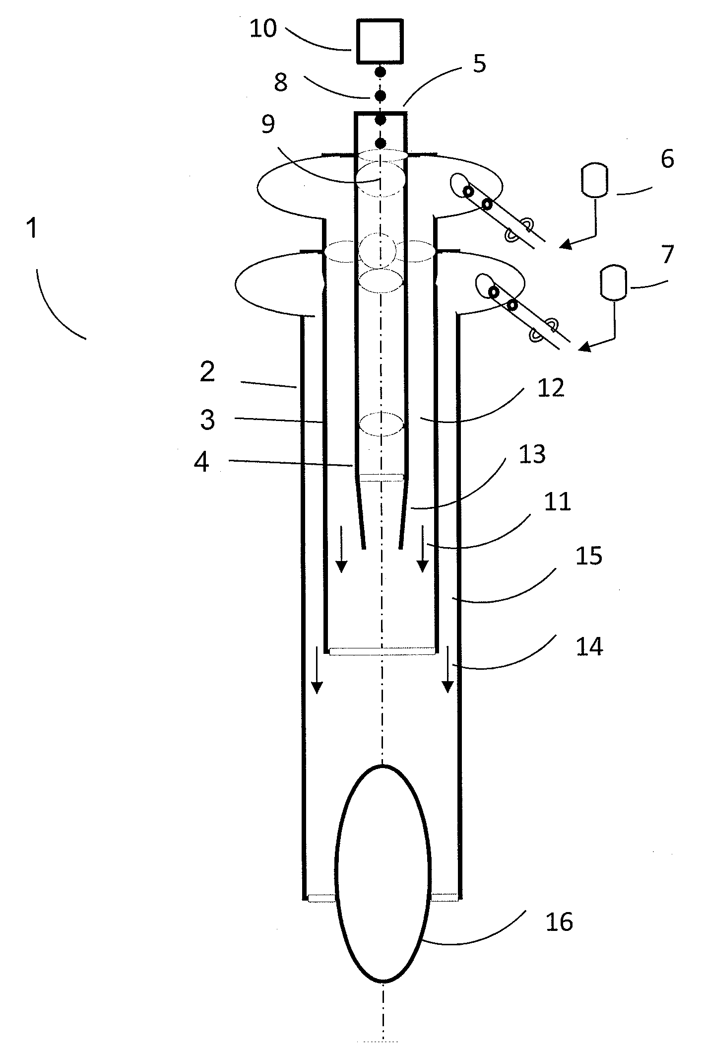
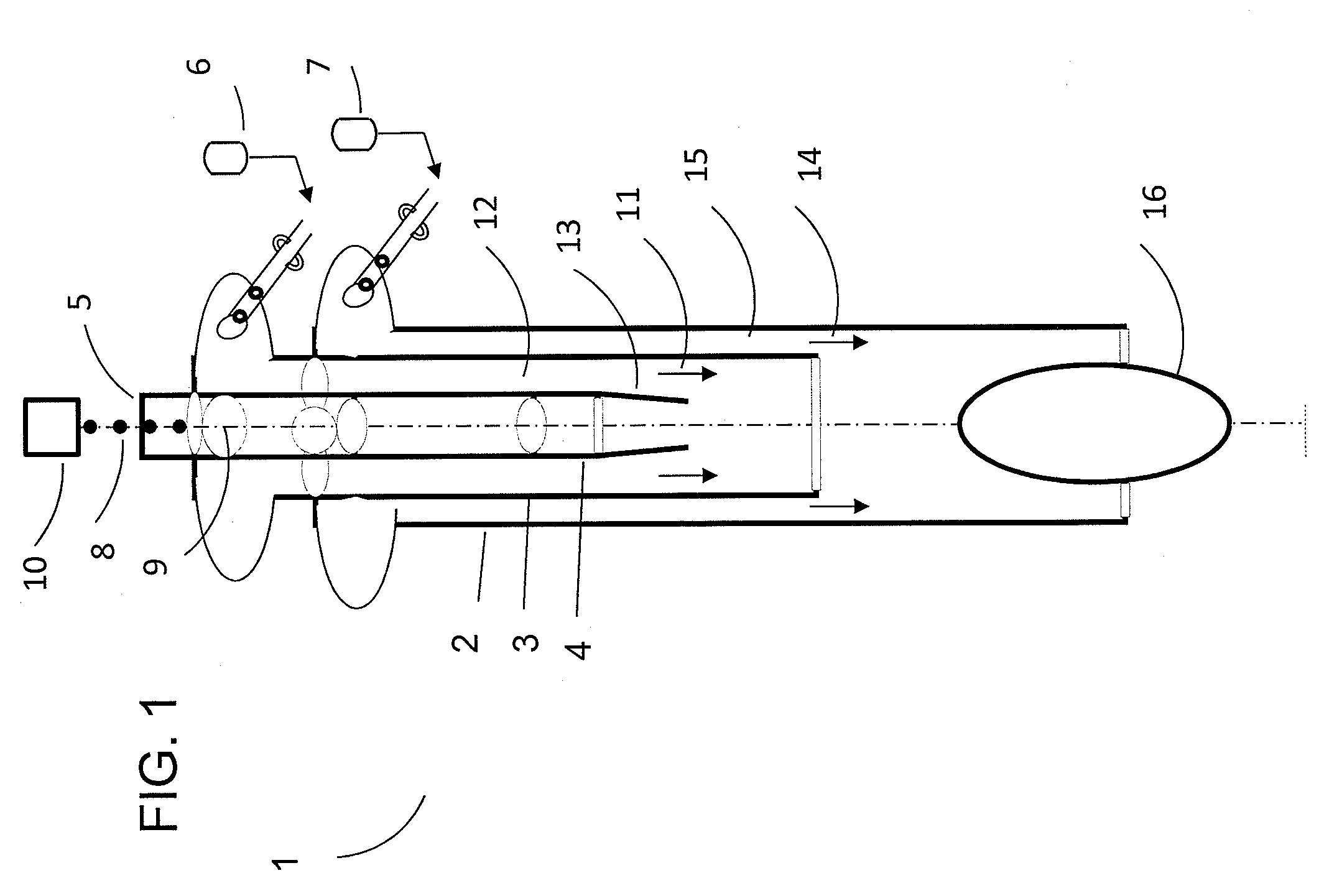
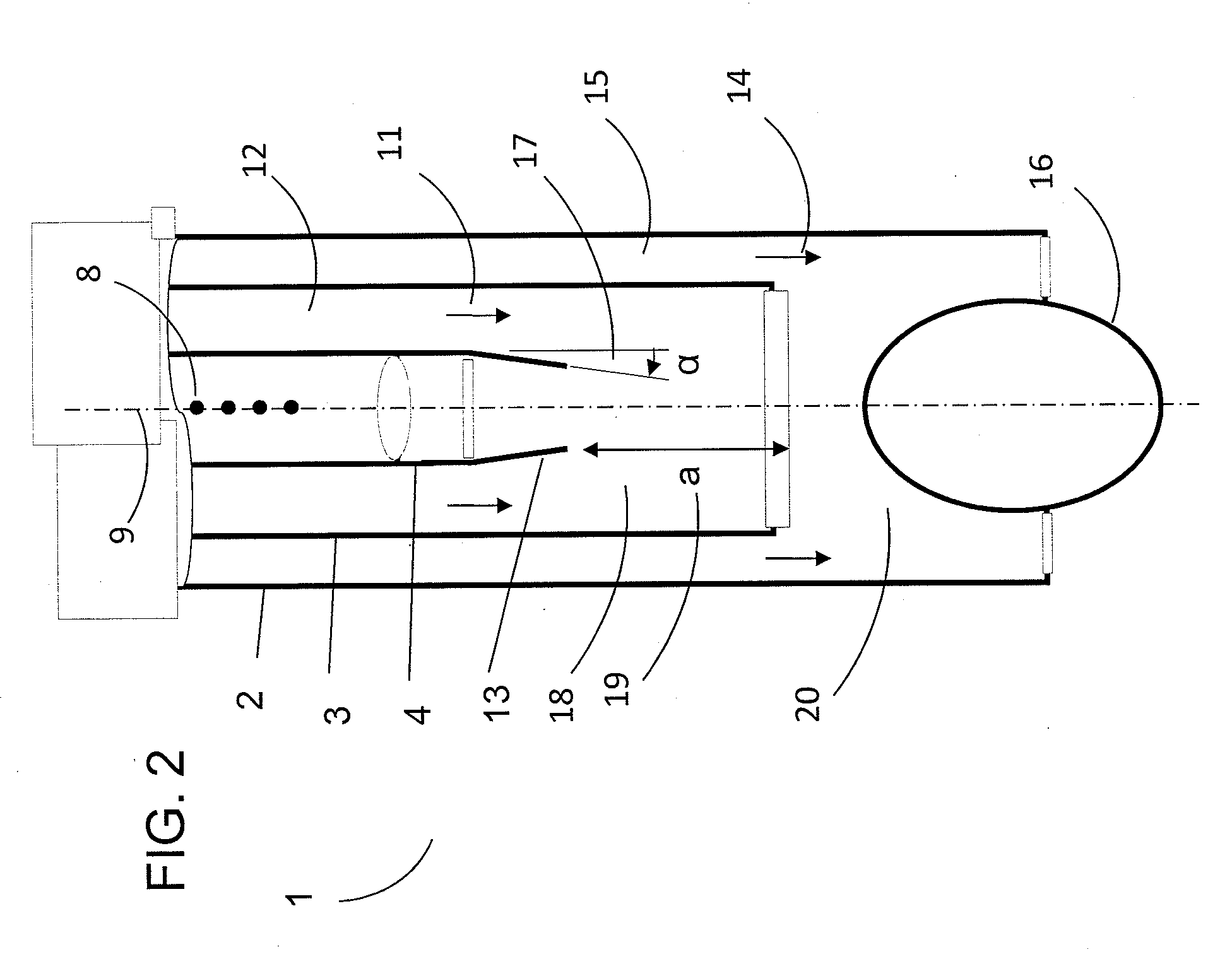
[0024]Referring to FIG. 1, a microwave plasma torch apparatus 1 for materials processing, in accordance with a preferred embodiment of the present invention, includes three concentric dielectric tubes 2, 3, and 4. The tubes are fused together at one end and provide input 5 for particle injection, as well as inputs 6 and 7 for process gas flows. Input 5 into tube 4 is used to inject process particles 8 (exemplary particles shown), along an alignment axis 9, using injection apparatus 10, which can be a solid particle feeder, such as a powder feeder, or a high frequency droplet maker. These devices are well known in the plasma processing arts. Input 6 is a pressurized source that provides a core laminar flow 11 through narrow gap 12, which accelerates process particles 8 at open end of tube 4, with laminar entrainment taking place in tube 3. The width of gap 12 is chosen to shield the injected particles in 4 from high velocity flow 14 while at the same time maximizing the entrainment v...


PUM


Abstract

A microwave plasma torch providing two laminar flows is described. Two laminar flows are created using a set of at least three concentric, staggered dielectric tubes connected to a pressurized gas source. An inner laminar flow entrains injected particles entering the plasma. An outer laminar flow creates a sheath around the plasma and prevents it from attaching to the walls of the plasma torch. The entry point of the gas source is designed to ensure laminar flow for both the entrainment of the particles and for the shielding of the plasma plume. The uniform processing conditions results in uniform particles and a homogenous materials distribution. This enables a final product with improved thermal properties, improved corrosion and wear resistance and a higher tolerance to interface stresses. The microwave plasma torch can be used for producing nanomaterial powder and for spray coating materials onto various substrates.

Description

TECHNICAL FIELD[0001]The present invention is generally directed to a microwave plasma torch used in materials processing. More particularly, the present invention is directed to a microwave plasma torch which generates laminar flow during materials processing. The laminar flow produced allows for the production of uniform particles and a homogenous materials distribution, which leads to improved characteristics in the final product. Even more particularly, the present invention is directed to a microwave plasma torch which can be used for nanomaterial powder production and for spray coating materials onto various substrates.BACKGROUND OF THE INVENTION[0002]When processing materials using a microwave plasma torch, a gas swirl flowing at high velocity prevents the plasma from attaching to the walls of the dielectric tube. This swirl gas subjects the materials to turbulent flow causing the materials to travel from the center of the tube, in line with the materials injection point, tow...

Claims


Application Information

Patent Timeline
IPC IPC(8): H05B6/64
CPCH05H1/30
Inventor HADIDI, KAMALREDJDAL, MAKHLOUF
Owner 6K INC
Why Eureka
Try Eureka