Pressure based liquid feed system for suspension plasma spray coatings

a technology of plasma spray coating and liquid feed system, which is applied in the direction of combustion types, applications, lighting and heating apparatus, etc., can solve the problems of reducing the cooling effect of feedstock on internal surfaces, clogging of injector orifices, and quick clogging of injectors, so as to prevent the build-up of obstruction materials

Active Publication Date: 2013-10-17
SULZER METCO (US) INC
View PDF5 Cites 29 Cited by
  • Summary
  • Abstract
  • Description
  • Claims
  • Application Information

AI Technical Summary

Benefits of technology

[0033]In accordance with another non-limiting aspect of the invention there is provided a method of using the apparatus or system of any one of the types described above. The method comprises at least one of; activating a flow of liquid cleaning fluid in a gas dispersant after a flow of liquid feedstock is stopped, automatically producing a flow of an atomized liqu

Problems solved by technology

Research found that injector proximity to plasma plume makes it necessary to maintain thermal management at all times. Any clogging upstream of the injector diminishes the flow of suspension through the injector orifice and reduces the cooling effect of a feedstock on inte

Method used


Image

  • Pressure based liquid feed system for suspension plasma spray coatings
  • Pressure based liquid feed system for suspension plasma spray coatings
  • Pressure based liquid feed system for suspension plasma spray coatings

Examples


Embodiment Construction

[0048]The particulars shown herein are by way of example and for purposes of illustrative discussion of the embodiments of the present invention only and are presented in the cause of providing what is believed to be the most useful and readily understood description of the principles and conceptual aspects of the present invention. In this regard, no attempt is made to show structural details of the present invention in more detail than is necessary for the fundamental understanding of the present invention, the description taken with the drawings making apparent to those skilled in the art how the several forms of the present invention may be embodied in practice.

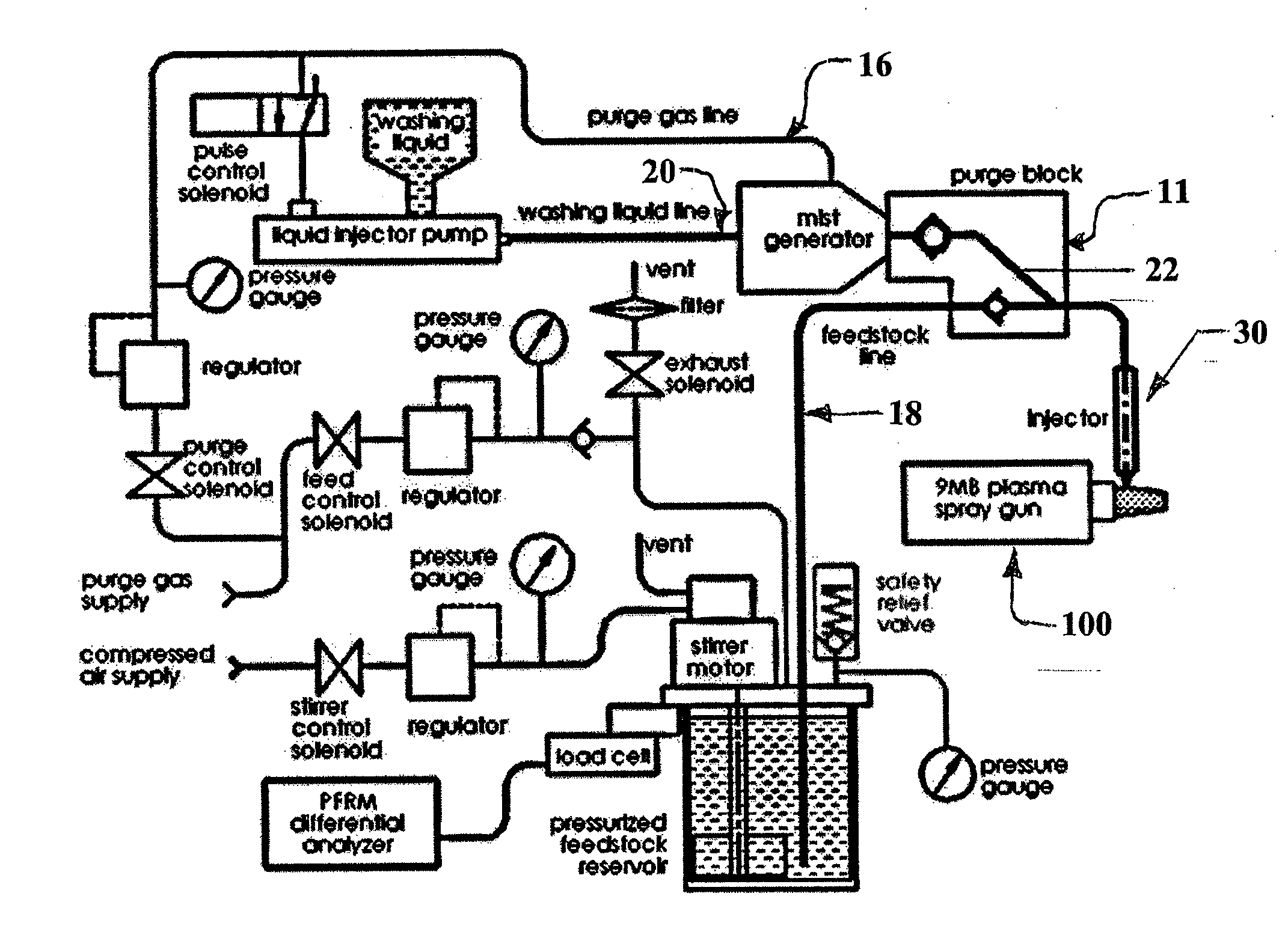
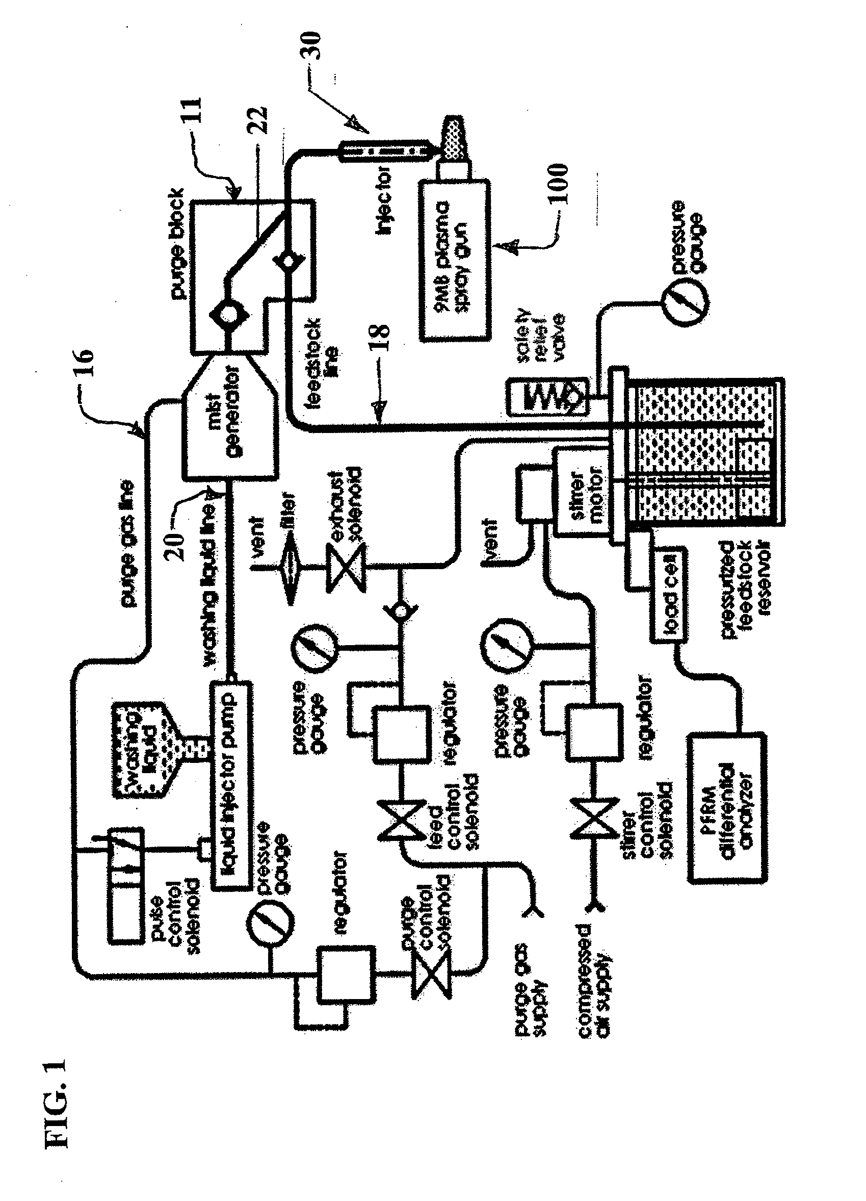
[0049]A liquid feeder proof of concept prototype was successfully developed and tested. It demonstrated that continuous and stable operation of a liquid based feedstock feeder is possible. A novel approach to semi-automated injector cleaning was developed and showed robustness on a level necessary for industrial thermal s...


PUM

PropertyMeasurementUnit
Timeaaaaaaaaaa
Flow rateaaaaaaaaaa
Areaaaaaaaaaaa

Abstract

Apparatus (1) for injecting a liquid in an area of a thermal spray gun (100). The apparatus (1) includes an injector cleaning device (10) having an inlet connectable (19) to at least one feedstock supply line (18), an inlet connectable (17) to at least one gas supply line (16), and an inlet connectable (21) to at least one liquid medium supply line (20). An injector (30) orifice is coupled to the injector cleaning device (10) and is adapted to at least one of inject a liquid jet into a hot stream created in the area of the thermal spray gun (100) and receive feedstock, gas and liquid passing into the inlets.

Description

CROSS-REFERENCE TO RELATED APPLICATIONS[0001]The instant application is an International Application based on U.S. provisional application No. 61 / 423,428, filed Dec. 15, 2010, the disclosure of which is hereby expressly incorporated by reference hereto in its entirety.STATEMENT REGARDING FEDERALLY SPONSORED RESEARCH OR DEVELOPMENT[0002]Work resulting in the instant invention was partially supported by funding from the National Institute of Standards and Technology under Advanced Technology Program number 70NANB7H7009.REFERENCE TO A COMPACT DISK APPENDIX[0003]Not applicable.BACKGROUND OF THE INVENTION[0004]The thermal spray process has been widely used to deposit coatings for industrial applications, including aerospace, automotive, petroleum and petrochemical, biomedical, etc. See Mateyja D., Plasma spraying of metallic and ceramic coatings. 1989, New York: John Wiley & Sons, the disclosure of which is hereby expressly incorporated by reference in its entirety. Thermal spray ceramic...

Claims


Application Information

Patent Timeline
IPC IPC(8): B05B15/02B05C11/00
CPCB05C11/00B05B15/02H05H1/42B05B7/226B08B9/00C23C4/11C23C4/134B05B15/555B05B15/557B05B15/25B05B7/0815B05B7/205B05B7/203B05B7/04H01L21/67051
Inventor COTLER, ELLIOT M.MOLZ, RONALD
Owner SULZER METCO (US) INC
Why Eureka
Try Eureka