
Multi-layer phase change material

a phase change material and multi-layer technology, applied in the field of recording materials, can solve the problems of affecting the reliability of the memory, restricting the further application of the pcram, and large power consumption, and achieve the effects of reducing heat interference, power consumption, and low thermal conductivity

Active Publication Date: 2013-10-17
HUAZHONG UNIV OF SCI & TECH
View PDF12 Cites 14 Cited by
  • Summary
  • Abstract
  • Description
  • Claims
  • Application Information

AI Technical Summary

Benefits of technology

The invention provides a multi-layer phase change material that can reduce heat interference between adjacent memory cells of PCRAM and power consumption. The material has low thermal conductivity and improves stability of the memory while reducing the temperature rise of adjacent memory cells. It also decreases the threshold voltage of PCRAM and reduces power consumption. The material is compatible with existing preparing methods and does not require the introduction of other non-phase change materials.

Problems solved by technology

Once temperature rise of the adjacent memory cells caused by heat transfer exceeds phase change temperature of a recording material, unintended variation of a recording state of the memory cell will occur, and heat interference between adjacent memory cells will greatly affect reliability of the memory.
As a result, large power consumption becomes another big bottleneck that restricts further application of the PCRAM.
Although temperature rise does not result in fast change of a state of the recording material, the method does not reduce heat transferred to adjacent memory cells, a resistance value of the recording material is significantly changed, and data bits are easy to fail after many times of operation, and thus a work life of the memory is greatly affected.
Nevertheless, as the crystallization temperature is raised, melting temperature of the film phase change material is correspondingly increased, which results in higher power consumption of the PCRAM.

Method used

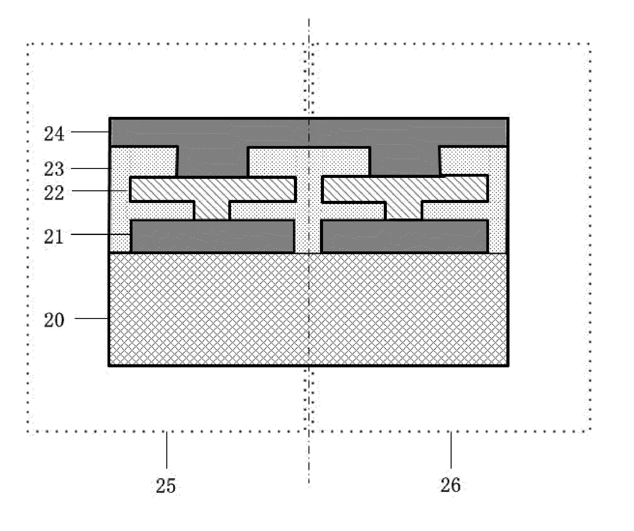

Image

  • Multi-layer phase change material
  • Multi-layer phase change material
  • Multi-layer phase change material

Examples


Embodiment Construction

[0034]Further description will be given below in conjunction with accompanying drawings and specific embodiments.

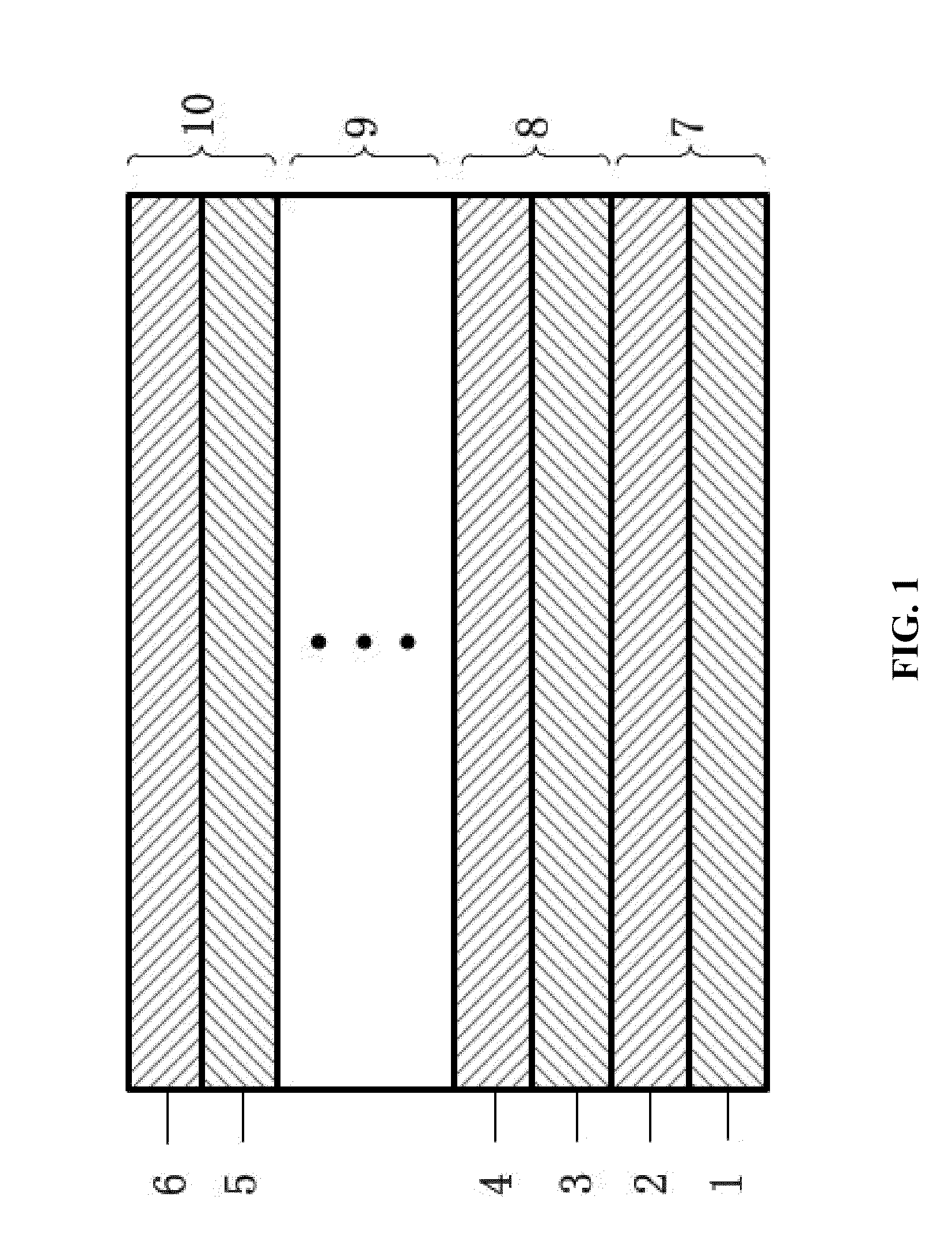
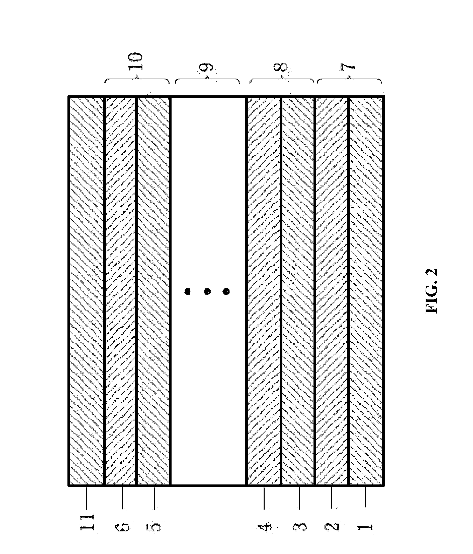
[0035]As shown in FIG. 1, the structure of a multi-layer phase change material of the invention is as follows: a second film material layer 2 is stacked on a first film material layer 1 whereby forming a first periodic unit 7, a third film material layer 3 is stacked on the second film material layer 2, and a fourth film material layer 4 is stacked on the third film material layer 3 whereby forming a second periodic unit 8, and so on . . . and finally N−3 (N≧10) periodic units 9 are formed on the fourth film material layer 4, and a last film material layer 6 is stacked on a last second film material layer 5 whereby forming a last periodic unit 10. The same film material layer in different periodic units is made of the same material, and two film material layers in the same periodic unit are made of different materials. For example, the first film material layer 1 of the f...


PUM


Abstract

A multi-layer phase change material, including: a multi-layer film structure. The multi-layer film structure includes a plurality of periodic units. The periodic units each includes a first single-layer film phase change material and a second single-layer film phase change material. The first single-layer film phase change material and the second single-layer film phase change material are alternately stacked. The first single-layer film phase change material includes chemical components that are different from chemical components included in the second single-layer film phase change material, or the first single-layer film phase change material includes chemical components that are the same as chemical components included in the second single-layer film phase change material and a percent composition of the chemical components included in the first single-layer film phase change material is different from a percent composition of the chemical components included in the second single-layer film phase change material.

Description

CROSS-REFERENCE TO RELATED APPLICATIONS[0001]This application is a continuation-in-part of International Patent Application No. PCT / CN2011 / 070450 with an international filing date of Jan. 21, 2011, designating the United States, now pending, and further claims priority benefits to Chinese Patent Application No. 201010595047.9 filed Dec. 17, 2010. The contents of all of the aforementioned applications, including any intervening amendments thereto, are incorporated herein by reference. Inquiries from the public to applicants or assignees concerning this document or the related applications should be directed to: Matthias Scholl P.C., Attn.: Dr. Matthias Scholl Esq., 14781 Memorial Drive, Suite 1319, Houston, Tex. 77079.BACKGROUND OF THE INVENTION[0002]1. Field of the Invention[0003]The invention relates to a recording material for a semiconductor memory, and more particularly, to a multi-layer phase change material having low thermal conductivity.[0004]2. Description of the Related Ar...

Claims


Application Information

Patent Timeline
Patent Type & Authority Applications(United States)
IPC IPC(8): H01L45/00
CPCH01L45/06H01L45/1608H10N70/823H10N70/231H10N70/861H10N70/8822H10N70/8825H10N70/884H10N70/883H10N70/826H10N70/8828H10N70/026H10N70/021
Inventor MIAO, XIANGSHUITONG, HAOCHENG, XIAOMIN
Owner HUAZHONG UNIV OF SCI & TECH
Learn More