
Methods for automated application of hardfacing material to drill bits

Active Publication Date: 2013-10-17
BAKER HUGHES INC
View PDF10 Cites 13 Cited by
  • Summary
  • Abstract
  • Description
  • Claims
  • Application Information

AI Technical Summary

Benefits of technology

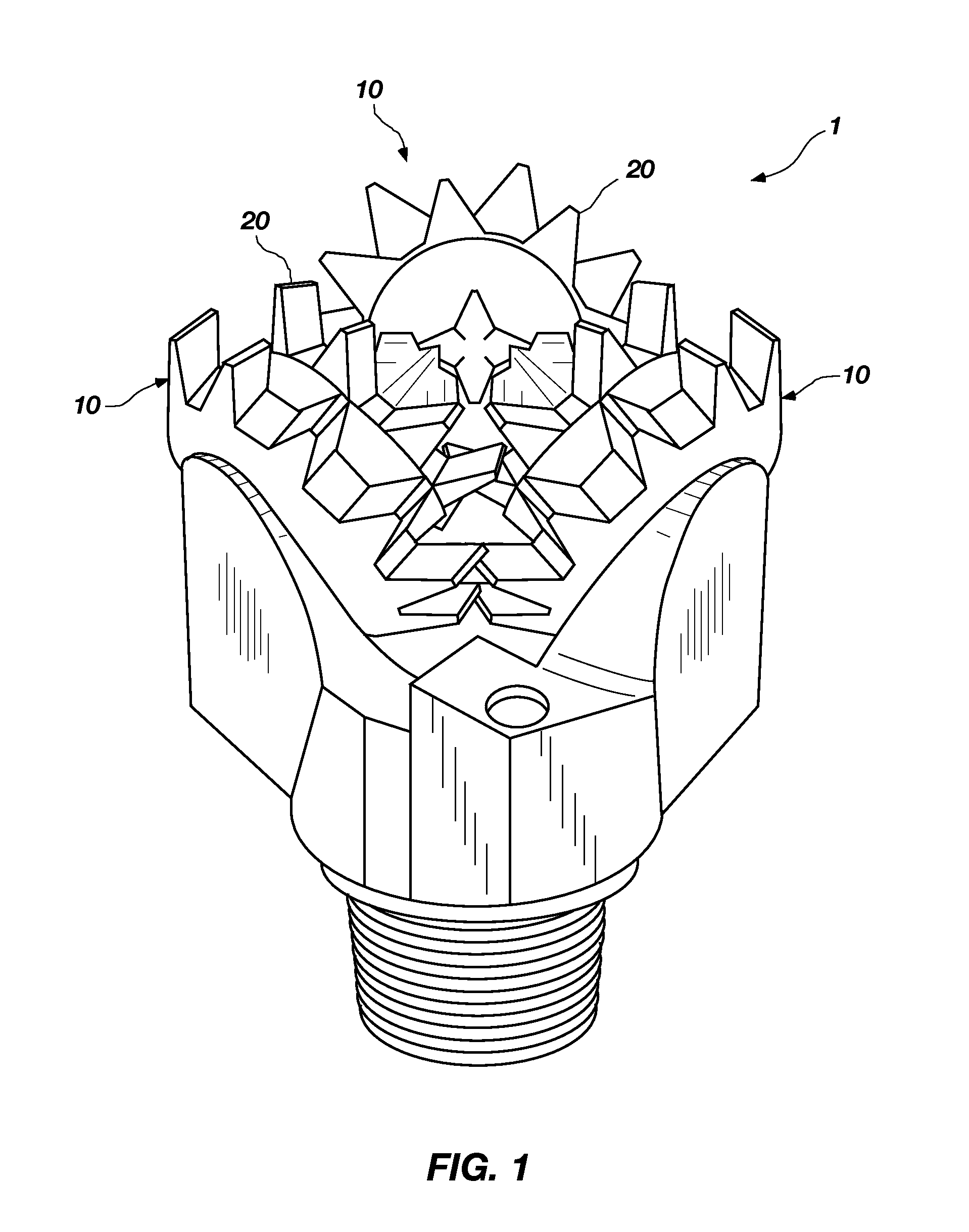
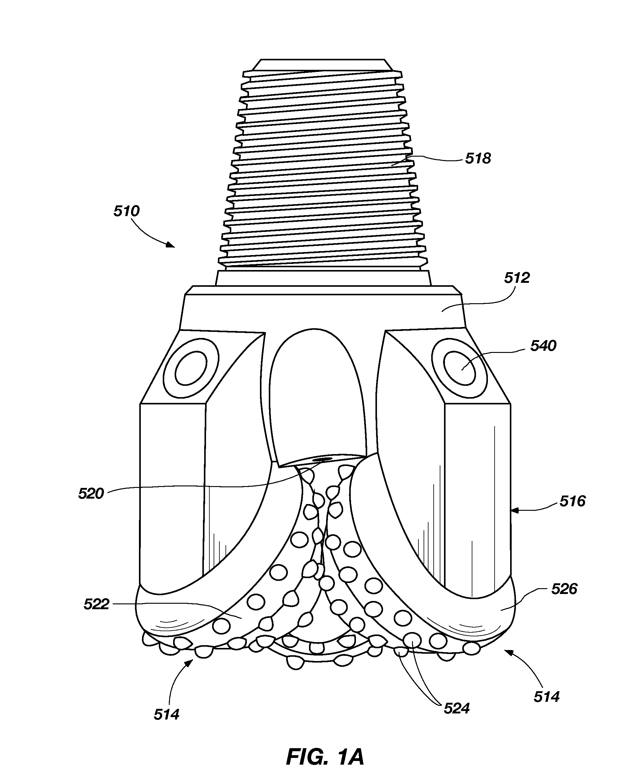
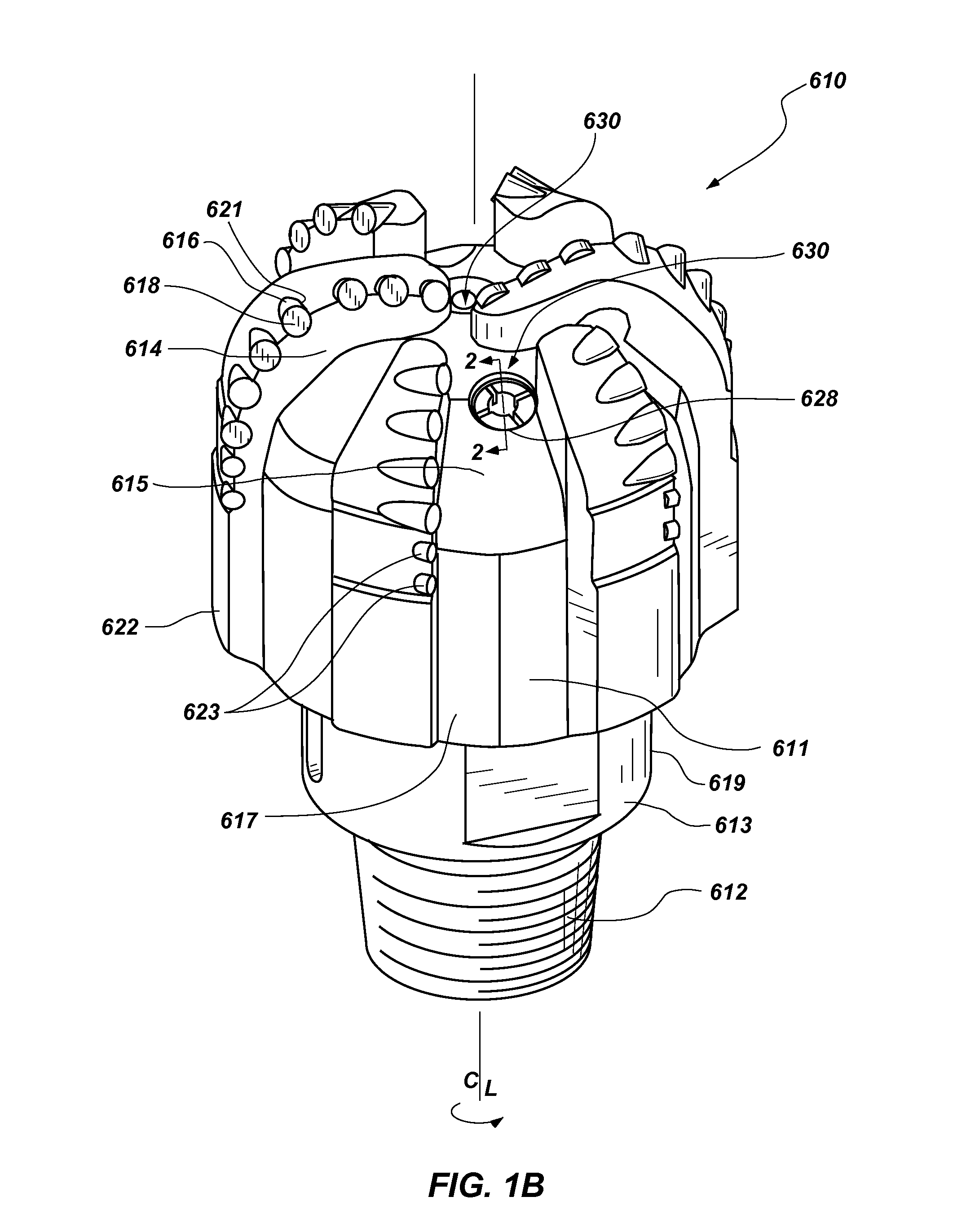
The patent describes different methods for depositing hardfacing material on drill bits and rock bits. The technical effects include improving wear resistance, increasing hardness, and reducing corrosion. These methods involve using a plasma transfer arc torch to deposit hardfacing material onto the surface of the bit. Different methods for positioning the torch and cutter are used to create patterns on the bit. The hardfacing material can be deposited on the teeth of the cutting tools or the thin and thick portions of a drill bit. This helps to prolong the lifespan of the bit and improve its performance in drilling activities.

Problems solved by technology

As the roller cones of the drill bit roll on the bottom of the hole being drilled, the teeth or carbide inserts apply a high compressive and shear loading to the formation causing fracturing of the formation into debris.
Under normal drilling conditions, the teeth of the steel-tooth roller cone drill bits are subject to continuous impact and wear because of their engagement with the rock being drilled.
As the teeth are worn away, the penetration rate of the drill bit decreases causing the cost of drilling to increase.
Limited availability of qualified welders has aggravated the problem because the application of hardfacing is extremely tedious, repetitive, skill-dependent, time-consuming, and expensive.
The application of hardfacing to roller cones is considered the most tedious and skill-dependent operation in the manufacture of a steel-toothed roller cone drill bit.
However, U.S. Pat. No. 6,392,190 does not describe details of solutions to the numerous obstacles in automating the hardfacing of roller cones using robotic arms and positioners.
One factor limiting use of robotic hardfacing has been the unsatisfactory appearance of the final product when applied using robotically held torches over stationary cutters.
Another factor limiting use of robotic hardfacing to rolling cutters is the commercial unavailability of a material that directly compares to conventional Oxygen Acetylene Welding (OAW) welding rod materials that can be applied with commercially available Plasma Transferred Arc (PTA) torches.
Another factor limiting use of robotic hardfacing is the inability to properly identify and locate individual roller cone designs within a robotic hardfacing system.
The roller cones of each size of drill bit and style of drill bit are substantially different, and initiating the wrong program could cause a collision of the torch and part, resulting in catastrophic failure and loss.
Another factor limiting use of robotic hardfacing is the inability to correct the critical positioning between the torch and roller cone in response to manufacturing variations of the cutter, wear of the torch, and buildup of hardfacing.
Still another factor limiting use of robotic hardfacing has been the inability to properly access many of the areas on the complex surface of a roller cone that require hardfacing with commercially available Plasma Transferred Arc (PTA) torches large enough to permit application of the required material.
Torches with smaller nozzles have smaller powder ports that prohibit proper flow of the desired powders.
Another factor limiting use of robotic hardfacing is the complexity of programming a control system to coordinate the critical paths and application sequences needed to apply the hardfacing.
A related factor limiting use of robotic hardfacing is the cost and limitation of resources.
These and several other obstacles have, until now, limited or prevented any commercial practice of automated hardfacing of roller cones.

Method used


Image

  • Methods for automated application of hardfacing material to drill    bits
  • Methods for automated application of hardfacing material to drill    bits
  • Methods for automated application of hardfacing material to drill    bits

Examples


Embodiment Construction

[0065]The system and method of the present invention have an opposite configuration and method of operation to that of manual hardfacing and prior automated hardfacing systems. In the present system and method a robotic system is used, having a plasma transfer arc torch secured in a substantially vertical position to a torch positioner in a downward orientation. The torch positioner is program-controllable in a vertical plane. Shielding, plasma, and transport gases are supplied to the torch through electrically controllable flow valves. Rather than use a torch positioner, a robotic arm can be used having a transfer arc torch secured thereto in a substantially vertical position in a downward orientation. For handling a roller cone, a robot having program controllable movement of an articulated arm is used. A chuck adapter is attached to the arm of the robot. A three jaw chuck is attached to the chuck adapter. The chuck is capable of securely holding a roller cone in an inverted posit...


PUM

PropertyMeasurementUnit
Timeaaaaaaaaaa
Lengthaaaaaaaaaa
Lengthaaaaaaaaaa

Abstract

Methods for depositing hardfacing material on portions of drill bits comprise providing a vertically oriented plasma transfer arc torch secured to a positioner having controllable movement in a substantially vertical plane. A rolling cutter is secured to a chuck mounted on an articulated arm of a robot. A surface of a tooth of the rolling cutter is positioned in a substantially perpendicular relationship beneath the torch. The torch is oscillated along a substantially horizontal axis. The rolling cutter is moved with the articulated arm of the robot in a plane beneath the oscillating torch. A hardfacing material is deposited on the tooth of the rolling cutter.

Description

CROSS-REFERENCE TO RELATED APPLICATIONS[0001]This application is a divisional of U.S. patent application Ser. No. 12 / 257,219, filed Oct. 23, 2008, which is scheduled to issue as U.S. Pat. No. 8,450,637 on May 28, 2013, the disclosure of which is incorporated herein in its entirety by this reference. The subject matter of this application is related to the subject matter of U.S. patent application Ser. No. 12 / 341,595, filed Dec. 22, 2008; U.S. patent application Ser. No. 12 / 603,734, filed Oct. 22, 2009, which claims benefit of U.S. Provisional Patent Application Ser. No. 61 / 109,427, filed Oct. 29, 2008; U.S. patent application Ser. No. 12 / 562,797, filed Sep. 18, 2009; and U.S. patent application Ser. No. 12 / 651,113, filed Dec. 31, 2009, the disclosure of each of which is incorporated herein in its entirety by this reference.FIELD[0002]The present invention relates to a system and method for the application of hardfacing to portions of a drill bit using robotic apparatus.BACKGROUND[00...

Claims


Application Information

Patent Timeline
IPC IPC(8): C23C4/12
CPCB05B7/222E21B17/1085C23C4/127B24D3/34B24D18/00C23C4/134
Inventor LUCE, DAVID KEITHGILMORE, KENNETH E.MASSEY, ALAN J.UNO, TIMOTHY P.NEHRING, KEITH L.
Owner BAKER HUGHES INC
Learn More