Automatic steering device and automatic steering method

a technology of automatic steering and steering device, which is applied in the direction of steering initiation, instruments, vessel construction, etc., can solve the problems of less maneuverability, constant fluctuation of the orientation of the ship, and burden on the helmsman, and achieve optimal duty ratio, optimal rudder turning speed at cruising speed can be found simply and accurately, and optimal duty ratio

Inactive Publication Date: 2013-10-24
FURUNO ELECTRIC CO LTD
View PDF7 Cites 14 Cited by
  • Summary
  • Abstract
  • Description
  • Claims
  • Application Information

AI Technical Summary

Benefits of technology

[0021]The present invention was conceived in light of the above situation, and its principal object is to provide an automatic steering device with which the optimal duty ratio for achieving the optimal rudder turning speed at cruising speed can be found simply and accurately. Another object of the present invention is to provid

Problems solved by technology

A ship that is underway is subjected to the effects of waves, wind, and other such external disturbances, which cause the orientation of the ship to fluctuate constantly.
Therefore, small steering inputs have to be made continuously in order to maintain a steady course (the direction in which the prow is facing), and this imposes a burden on the helmsman.
If the rudder turning speed is too slow, the vessel is less maneuverable, but if the rudder turning speed is too fast, the vessel becomes unstable.
However, because the operation test method illustrated by the flowchart in FIG. 6 involves repeating measurement of the rudder turning speed while the duty ratio is lowered by 10% each time, the optimal duty ratio cannot be found at a precision that is finer than 10%.
Therefore, the operation test method depicted in FIG. 6 cannot necessarily be called a precise test method.
Therefore, a problem is that it ta

Method used


Image

  • Automatic steering device and automatic steering method
  • Automatic steering device and automatic steering method
  • Automatic steering device and automatic steering method

Examples


Embodiment Construction

[0048]Selected embodiments will now be explained with reference to the drawings. It will be apparent to those skilled in the art from this disclosure that the following descriptions of the embodiments are provided for illustration only and not for the purpose of limiting the invention as defined by the appended claims and their equivalents.

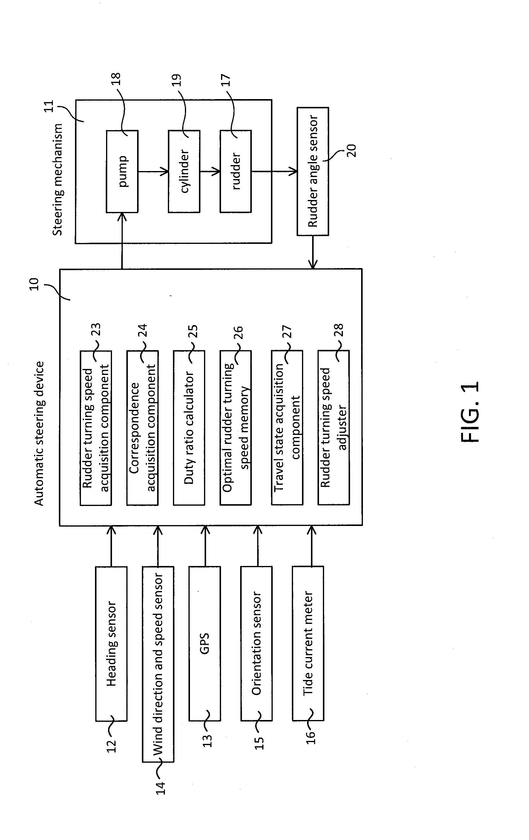
[0049]An embodiment of the present invention will be described through reference to the drawings. FIG. 1 is a block diagram of the functions of the configuration of an automatic steering system equipped with the automatic steering device 10 pertaining to the present invention.

[0050]This automatic steering device 10 is attached to the hull of a boat or ship that is being controlled. In addition to the automatic steering device 10, this vessel also includes a steering mechanism 11 and various kinds of running situation detector for acquiring the running situation of the vessel (such as a heading sensor 12, a GPS receiver 13, a wind direction and spe...


PUM


Abstract

There is provided an automatic steering device with which an optimal duty ratio for achieving an optimal rudder turning speed at a cruising speed can be found simply and accurately. An automatic steering device 10 includes a correspondence acquisition component 24 and a duty ratio calculator 25. The correspondence acquisition component 24 finds a correspondence between a duty ratio and a rudder turning speed based on a first rudder turning speed while a steering mechanism 11 is controlled at a first duty ratio, and a second rudder turning speed while the steering mechanism 11 is controlled at a second duty ratio. The duty ratio calculator 25 calculates the duty ratio corresponding to a specific rudder turning speed based on the correspondence found by the correspondence acquisition component 24.

Description

CROSS-REFERENCE TO RELATED APPLICATIONS[0001]This application claims priority to Japanese Patent Application No. 2012-097135 filed on Apr. 20, 2012. The entire disclosure of Japanese Patent Application No. 2012-097135 is hereby incorporated herein by reference.BACKGROUND[0002]1. Field of the Invention[0003]The present invention generally relates to an operation test for determining the duty ratio of drive voltage applied to a steering mechanism in an automatic steering device.[0004]2. Background Information[0005]A ship that is underway is subjected to the effects of waves, wind, and other such external disturbances, which cause the orientation of the ship to fluctuate constantly. Therefore, small steering inputs have to be made continuously in order to maintain a steady course (the direction in which the prow is facing), and this imposes a burden on the helmsman. There are known automatic steering devices that provide feedback control of the steering mechanism so as to maintain a pr...

Claims


Application Information

Patent Timeline
IPC IPC(8): B63H25/04
CPCB63H25/04G05D1/0206Y02T70/00
Inventor EKUNI, SUMINORISHIMO, KAZUTOSHIHAMAMOTO, KENTAROH
Owner FURUNO ELECTRIC CO LTD
Why Eureka
Try Eureka