Dual-mask arrangement for solar cell fabrication

a solar cell and dual-mask technology, applied in the field of mask fabrication, can solve the problems of mask warping, loose contact with wafers, and many challenges of mask use, and achieve the effect of easy and fast loading and unloading of substrates

Active Publication Date: 2013-10-24
INTEVAC
View PDF45 Cites 318 Cited by
  • Summary
  • Abstract
  • Description
  • Claims
  • Application Information

AI Technical Summary

Benefits of technology

[0012]Magnets are located in the susceptor and alternate N-S-N-S-N completely around the frame or completely below the entire surface of the susceptor and directly under the wafer. The outer and inner masks are designed to be held to the frame by magnetic forces only, so as to enable easy and fast loading and unloading of substrates.
[0013]The mask assembly is removable from the wafer carrier and support frame to load the substrate into the carrier. Both the outer and inner masks are lifted as part of the mask assembly. Once the wafer is located on the carrier in the wafer pocket, the mask assembly is lowered back down onto the carrier. The inner mask overlaps the top surface of the wafer. The magnets in the carrier frame pull the inner mask down into intimate contact with the substrate. This forms a tight compliant seal on the edge of the wafer. The outer mask is designed in order

Problems solved by technology

One way to create this exclusion zone is through the use of a mask; however, using masks has many challenges.
As explained a

Method used


Image

  • Dual-mask arrangement for solar cell fabrication
  • Dual-mask arrangement for solar cell fabrication
  • Dual-mask arrangement for solar cell fabrication

Examples


Embodiment Construction

[0028]While in traditional semiconductor manufacturing wafers are generally processed independently, in solar fabrication multiple wafers are fabricated simultaneously. For simplicity, the following will be described with respect to processing of three wafers simultaneously; however, it should be appreciated that the embodiments may be extended to any number of wafers being processed simultaneously.

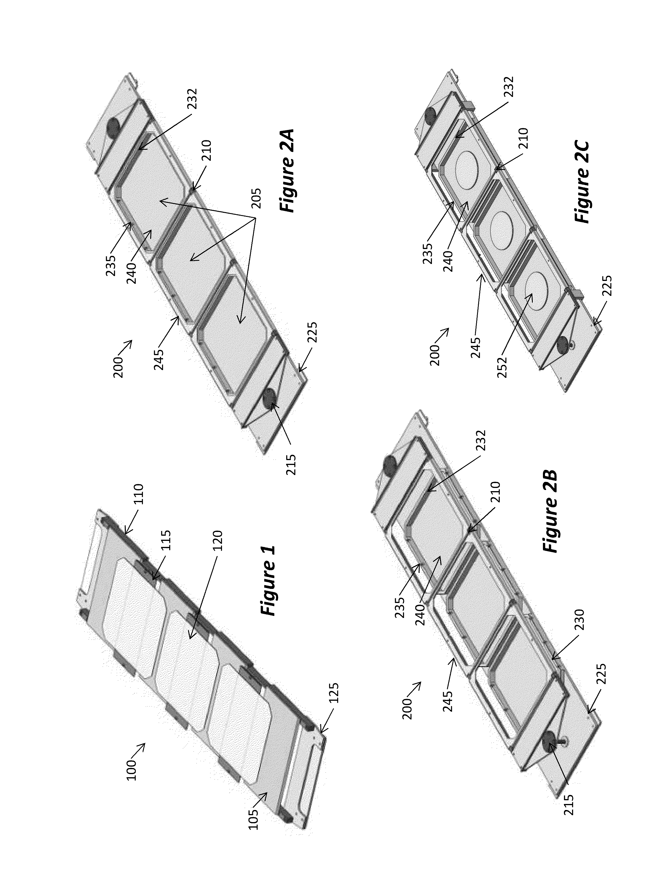
[0029]FIG. 1 illustrates a multi-wafer carrier according to one embodiment, which is not configured for mask processing. That is, in the fabrication of solar cells, some of the processing steps do not require masking of the wafers. In such cases, the carrier of FIG. 1 can be used. Carriers which implement the dual-mask arrangement will be described below with reference to the remaining Figures. Thus, in various embodiments, processing steps that do not require masking would be performed using the carriers of FIG. 1, while processing steps that require masking would be performed sing the c...


PUM

PropertyMeasurementUnit
Fractionaaaaaaaaaa
Thicknessaaaaaaaaaa
Thicknessaaaaaaaaaa

Abstract

An arrangement for supporting substrates during processing, having a wafer carrier with a susceptor for supporting the substrate and confining the substrate to predetermined position. An inner mask is configured for placing on top of the substrate, the inner mask having an opening pattern to mask unprocessed parts of the substrate, but expose remaining parts of the substrate for processing. An outer mask is configured for placing on top of the inner mask, the outer mask having an opening that exposes the part of the inner mask having the opening pattern, but cover the periphery of the inner mask.

Description

RELATED APPLICATIONS[0001]This application claims priority benefit from U.S. Provisional Application Ser. No. 61 / 635,804, filed Apr. 19, 2012, and U.S. Provisional Application Ser. No. 61 / 639,052, filed Apr. 26, 2012, the entire disclosure of which is incorporated herein by reference.BACKGROUND[0002]1. Field[0003]This application relates to masking fabrication, such as using masks in the fabrication of solar cells.[0004]2. Related Art[0005]During various fabrication stages of solar cells, it may be desired to use masks so as to block parts of the solar cells from the particular fabrication process. For example, masks may be used for formation of contacts or for edge exclusion to preventing shunting of the cell. That is, for cells having contacts on the front and back sides, materials used for making the contacts may be deposited on the edges of the wafer and shunt the front and back contacts. Therefore, it is advisable to use mask to exclude the edges of the cell during fabrication ...

Claims


Application Information

Patent Timeline
IPC IPC(8): H01L31/18
CPCH01L31/1892C23C14/042H01L21/6734H01L21/67346H01L31/18Y02E10/50C23C14/50C23C16/042C23C16/4585
Inventor BLUCK, TERRYLATCHFORD, IANSHAH, VINAYRIPOSAN, ALEX
Owner INTEVAC
Why Eureka
Try Eureka