Display device and method for controlling display device

a display device and display device technology, applied in the direction of instruments, computing, electric digital data processing, etc., can solve the problems of increasing the cost required for driving the light emitting diodes, the load on the light source units is becoming excessive, and the noise to occur, so as to reduce the current capacity, suppress the increase in the cost required for driving the first and second light source units, and reduce the current capacity

Active Publication Date: 2013-10-24
PANASONIC INTELLECTUAL PROPERTY CORP OF AMERICA
View PDF13 Cites 3 Cited by
  • Summary
  • Abstract
  • Description
  • Claims
  • Application Information

AI Technical Summary

Benefits of technology

[0010]According to the display device and the method for controlling the display device of the present application, in the overlapped period, a PWM signal, to turn the first and second light source units on and off with a predetermined pulse width, is outputted, and the phase of the PWM signal to be outputted to the first light source unit and the phase of the PWM signal to be outputted to the second light source unit are shifted from each other. Therefore, even though the one frame period has the overlapped period, the degree of increase o...

Problems solved by technology

If all the light emitting diodes were driven at a same timing, pulsed driving control with large current as a whole would be performed, which would cause n...

Method used


Image

  • Display device and method for controlling display device
  • Display device and method for controlling display device
  • Display device and method for controlling display device

Examples


first embodiment

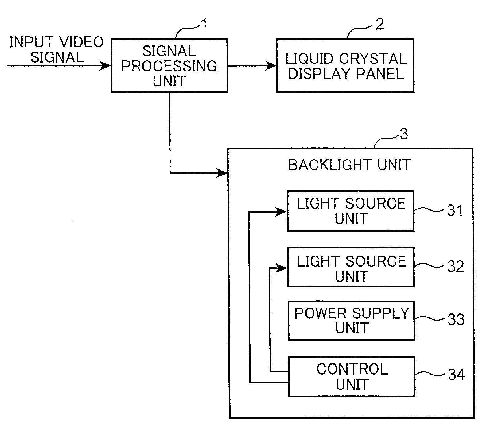
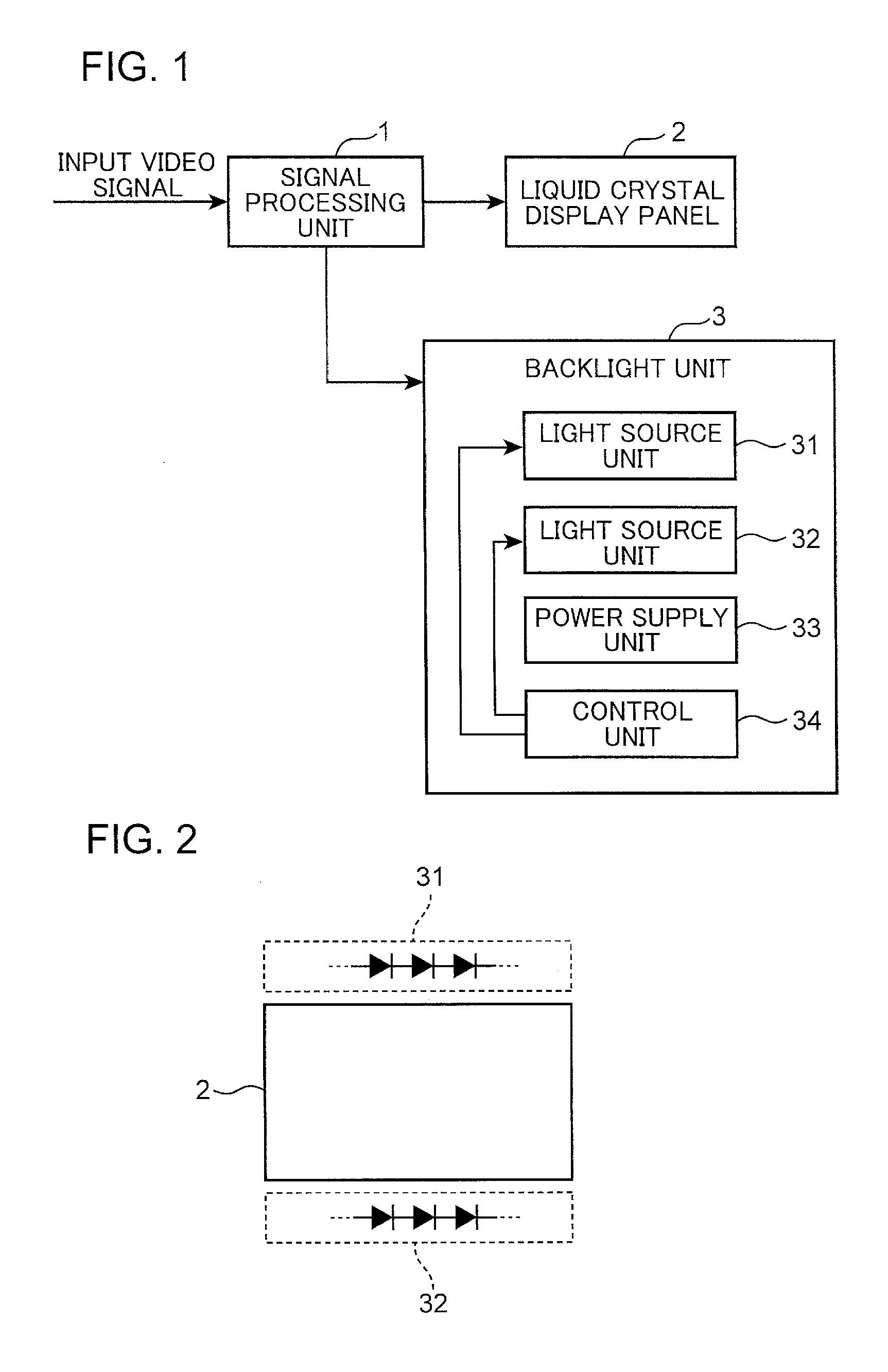
[0019]FIG. 1 is a block diagram depicting a configuration of a display device according to a first embodiment of the present application. FIG. 2 is a schematic diagram depicting an arrangement of the light source units of a backlight unit according to the first embodiment.

[0020]A display device shown in FIG. 1 has a signal processing unit 1, a liquid crystal display panel 2, and a backlight unit 3. Based on an input video signal from the outside, the signal processing unit 1 generates a control signal to control the liquid crystal display panel 2 and a control signal to control the backlight unit 3, and outputs the control signals to the liquid crystal display panel 2 and the backlight unit 3 respectively. Although not illustrated in FIG. 1, the liquid crystal display panel 2 has a plurality of gate lines that extend in the horizontal direction, a plurality of source lines that extend in the vertical direction, switching elements and a plurality of pixels, where the plurality of pix...

second embodiment

[0044]In the above first embodiment, the backlight unit 3 has two light source units, that is, the light source unit 31 arranged along the top edge of the liquid crystal display panel 2, and the light source unit 32 arranged along the bottom edge of the liquid crystal display panel 2, but the present application is not limited to this. The backlight unit may have three or more light source units, for example.

[0045]FIG. 5 is a block diagram depicting a configuration of the display device according to a second embodiment of the present application. FIG. 6 is a schematic diagram depicting an arrangement of light source units of a backlight unit according to the second embodiment. In the second embodiment, a composing element similar to the first embodiment is denoted with a similar reference symbol. The display device of the second embodiment of the present application will now be described focusing on the differences from the first embodiment.

[0046]The display device of the second emb...


PUM


Abstract

A display device has a display panel and a backlight unit. The backlight unit includes first and second light source units, and a control unit that outputs a drive signal to the light source units to drive the first and second light source units during first and second drive periods in one frame period respectively. The control unit drives the light source units so that the one frame period has an overlapped period, in which the first and second drive periods overlap. The control unit outputs PWM signals to turn the light source units on and off to the light source units respectively. The control unit shifts a phase of the PWM signal to be outputted to the first light source unit and a phase of the PWM signal to be outputted to the second light source unit from each other.

Description

BACKGROUND[0001]1. Technical Field[0002]This disclosure relates to a display device having a backlight unit that illuminates a display panel from the rear face, and a method for controlling the display device.[0003]2. Description of the Related Art[0004]A display device, having a display panel that uses non-self-light-emitting liquid crystal as a light modulation element, includes a backlight unit that illuminates the display panel from the rear face, and displays arbitrary images by controlling the transmittance of the light emitted from the backlight unit using the liquid crystal. For the light source of the backlight unit, light emitting diodes, for example, are used, hence various techniques to control driving of the light emitting diodes have been proposed (e.g. see Japanese Patent Application Laid-Open No. 2008-91311).[0005]In the case of the light emitting diode drive device according to Japanese Patent Application Laid-Open No. 2008-91311, a plurality of light emitting diode...

Claims


Application Information

Patent Timeline
IPC IPC(8): G09G3/36
CPCG09G3/36G09G3/3426G09G2320/0633G09G2320/064G09G2330/025G09G3/342G09G2310/024
Inventor YAMAMURA, AKIHIROMATSUDA, ISAO
Owner PANASONIC INTELLECTUAL PROPERTY CORP OF AMERICA
Why Eureka
Try Eureka