Thin film battery package

a thin film battery and battery pack technology, applied in the direction of batteries, sustainable manufacturing/processing, cell components, etc., can solve the problems of reducing the size of power sources, reducing the limiting the miniaturization of existing lithium secondary batteries, so as to prevent rapid deterioration in durability and charge/discharge efficiency of thin film battery packages, the effect of easy welding

Inactive Publication Date: 2013-10-24
APPLIED MATERIALS INC
View PDF1 Cites 8 Cited by
  • Summary
  • Abstract
  • Description
  • Claims
  • Application Information

AI Technical Summary

Benefits of technology

[0016]According to embodiments of the present invention, unit cells constituting a thin film battery package is present in a sealed state, thereby enabling complete protection of the unit cells from an external environment, and particularly, from external impact or abrasion.
[0017]In addition, the unit cells are in a vacuum state or an inert gas-filled state, thereby enabling prevention of rapid deterioration in durability and charge / discharge efficiency of the thin film battery package.
[0018]Further, plural unit cells are stacked inside a single sealed case, whereby the capacity of the thin film battery package can be maximized, and the thin film battery package can be used as a power source for various electrical devices.
[0019]Furthermore, since the case is formed by sintering, the locations and shape of electrodes on the case can be variously modified, whereby the thin film battery package can be used as a power source for various electrical devices.
[0020]Also, Kovar alloy is formed at an upper end of the case, so that the case can be easily welded to a cover made of metal.
[0021]Further, it is possible to prevent contact between a metal surface in an internal space of the case and conductive paste coating layers electrically connecting the unit cells stacked inside the case, thereby preventing electrical short-circuit.

Problems solved by technology

However, the size of power sources is not decreased in proportion to the miniaturization and portability of electronic devices.
Existing lithium secondary batteries have restriction in miniaturization due to a complex structure thereof.
In addition, it is difficult to fabricate a thin lithium secondary battery due to the use of a pouch, and there is a risk of explosion.
However, when the thin film battery is used under a general atmospheric environment or high-temperature atmosphere, micro-pinholes can be produced in the protective film during the formation of the protective film, or curing or deformation can occur in the protective film of a polymer material due to high temperature.
Therefore, some components constituting the thin film battery can be exposed to the external environment due to deficiency of the protective film.
Moreover, a conventional thin film battery composed of unit cells has a limited applicability as a power source for electronic devices due to low capacity.

Method used


Image

  • Thin film battery package
  • Thin film battery package
  • Thin film battery package

Examples


Embodiment Construction

(Ceramic Package)3.1 × 10⁻⁸ atm cc / secComparative Example 1 (Epoxy Package)2.5 × 10⁻⁵ ata cc / sec

[0153]The thin film battery package according to the present invention may have a gas transmission rate ranging from 5×10⁻⁷ atmcc / sec to 10−9 atmcc / sec.

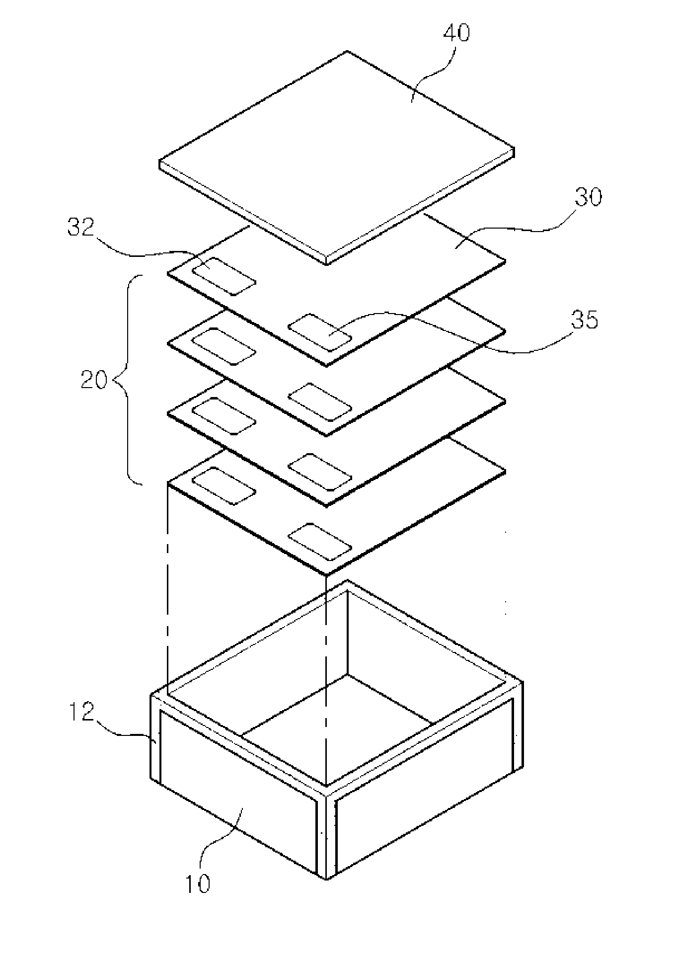
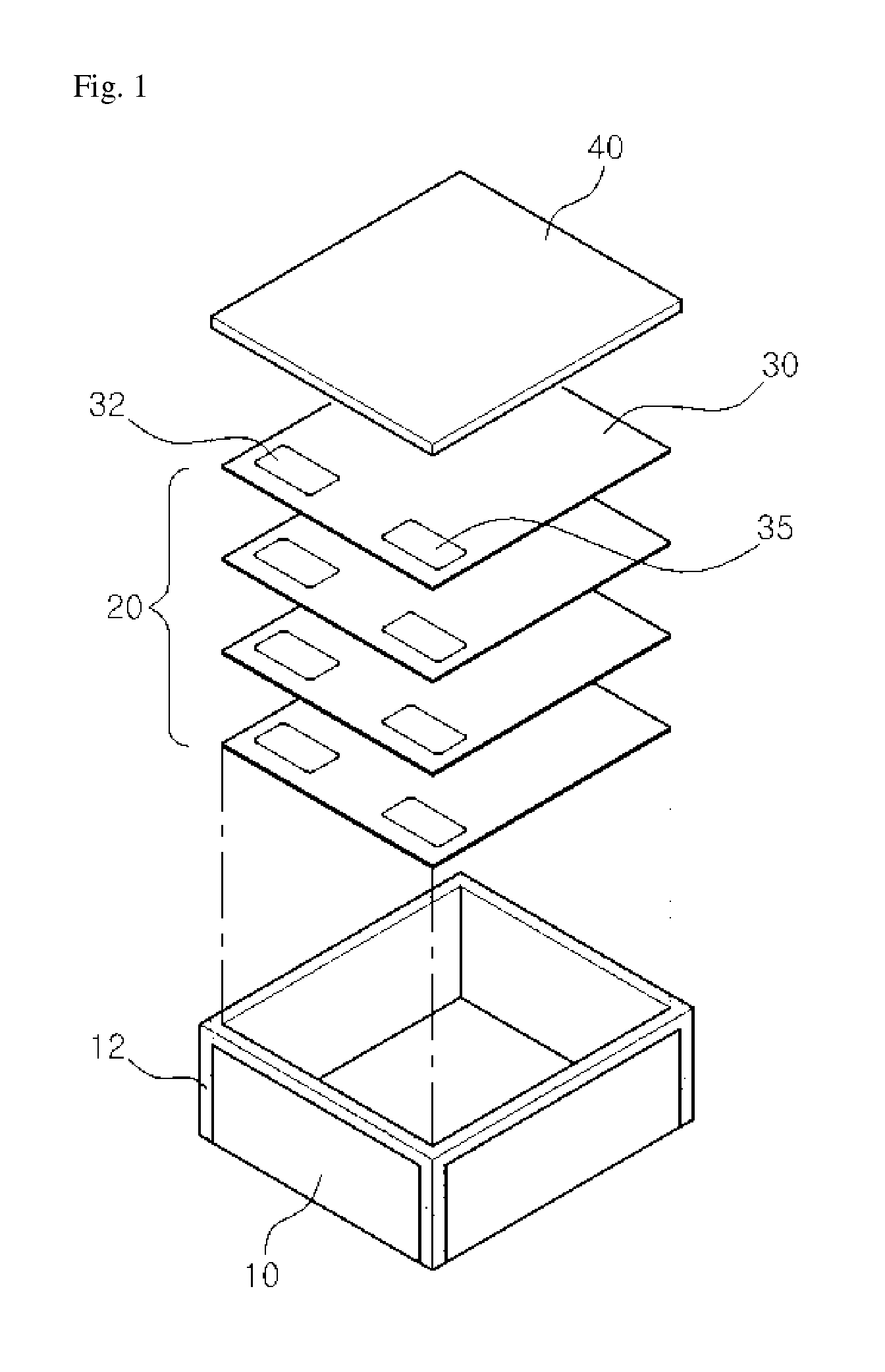
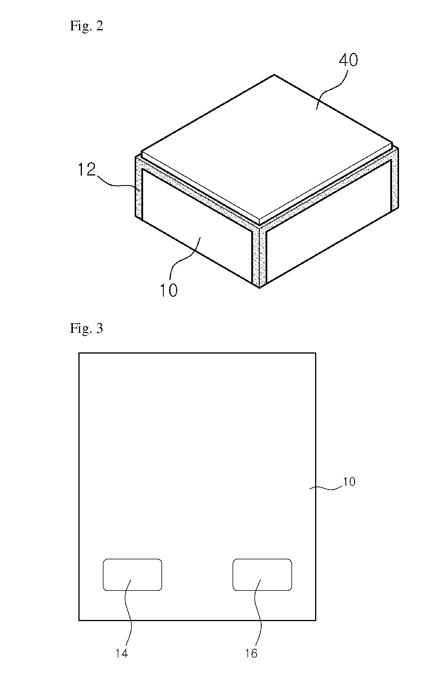
[0154]In the present invention, the case is made of an insulating material such as ceramic, the support member is made of a Kovar alloy, and the cover is made of metal or ceramic.

[0155]Thus, the present invention provides a thin film battery package through welding and coupling between ceramic and metal.

[0156]In the present invention, there are provided results obtained by performing an experiment of estimating shielding and preserving characteristics, using the thin film battery package.

[0157]

[0158]First, one packaged battery block was loaded into a pressure chamber made of metal.

[0159]Then, the pressure chamber was completely hermetically sealed.

[0160]Subsequently, 99.9% pure helium gas was injected into the pressure chamber until the pr...


PUM

PropertyMeasurementUnit
charge/aaaaaaaaaa
thicknessaaaaaaaaaa
durabilityaaaaaaaaaa

Abstract

A thin film battery package includes: a case having an open top side and defining a predetermined space therein, wherein the case has one side at which first and second electrodes formed of a metal material are exposed and electrically connected to the outside; a battery block on which a plurality of unit batteries are stacked so that the plurality of unit batteries is electrically connected between a first terminal and a second terminal, wherein the battery block is seated within the case so that the first and second terminals of the unit battery disposed at one end thereof are electrically connected to the first and second electrodes; and a cover sealed and coupled to the top surface of the case.

Description

TECHNICAL FIELD[0001]The present invention relates to a thin film battery package, and more particularly, to a thin film battery package, which includes a plurality of unit cells modularized and inserted into one case to maximize capacity of a thin film battery, and which is sealed from the outside, whereby components constituting a thin film battery are not influenced by an external environment, thereby improving durability and charge / discharge efficiency of the thin film battery.BACKGROUND ART[0002]With the development of electronic and information communication industries, individuals carry various kinds of personal digital assistants, office devices, and the like. Therefore, miniaturization of devices has been rapidly advanced in many fields including cellular phones, portable AV devices, portable OA devices, and the like.[0003]However, the size of power sources is not decreased in proportion to the miniaturization and portability of electronic devices. Accordingly, there is an ...

Claims


Application Information

Patent Timeline
Patent Type & Authority Applications(United States)
IPC IPC(8): H01M2/02H01M50/105H01M50/211H01M50/296H01M50/528H01M50/55H01M50/557
CPCH01M2/0207H01M2220/30H01M10/052H01M10/0562Y02E60/10H01M50/124Y02P70/50H01M50/105H01M50/557H01M50/211H01M50/55H01M50/296H01M50/147H01M50/183H01M50/54H01M50/545H01M50/579H01M10/05
Inventor KIM, SOO HONAM, SANG-CHEOLKIM, YONG YEONCHO, EUN HANG
Owner APPLIED MATERIALS INC
Why Eureka
Try Eureka