Method and system for non-invasive imaging of a target region

a target region and imaging technology, applied in the field of non-invasive imaging of the target region, can solve the problems of image blurring, severe affecting clinical diagnosis, and difficult task of setting detector settings

Active Publication Date: 2013-10-31
GENERAL ELECTRIC CO
View PDF12 Cites 28 Cited by
  • Summary
  • Abstract
  • Description
  • Claims
  • Application Information

AI Technical Summary

Problems solved by technology

Although the conventional detector cells provide varied functionality, a particularly challenging task is to configure detector settings for imaging a targeted ROI that is less than the full scan field of view (FOV) of the imaging system in high spatial resolution.
Accordingly, application of conventional reconstruction methods may result in image blurring and other artifacts that can severely affect clinical diagnosis, especially if the imaged features are small.
For example, plaques formed in coronary arteries are generally indicative of a risk of a potential heart attack, but are difficult to image due to their small size.
Certain conventional imaging systems, for example, have employed expensive detector configurations, heavier or higher power tubes combined with fast spinning of a gantry, and complex iterative reconstructions to generate high-resolution images.
These techniques, however, incur considerable costs, are mechanically restrictive and / or rely on additional imaging time and radiation dosage, especially for reconstructing small features such as lesions and nodules in regions of interest.

Method used


Image

  • Method and system for non-invasive imaging of a target region
  • Method and system for non-invasive imaging of a target region
  • Method and system for non-invasive imaging of a target region

Examples


Embodiment Construction

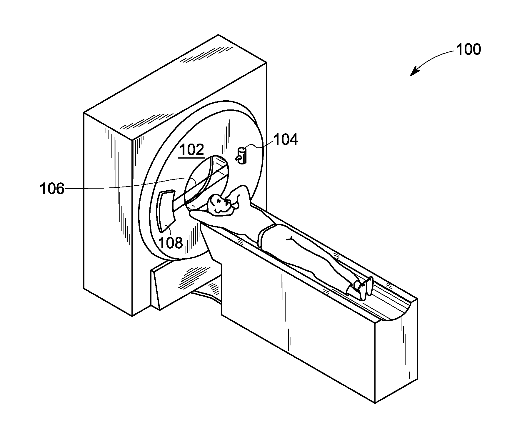
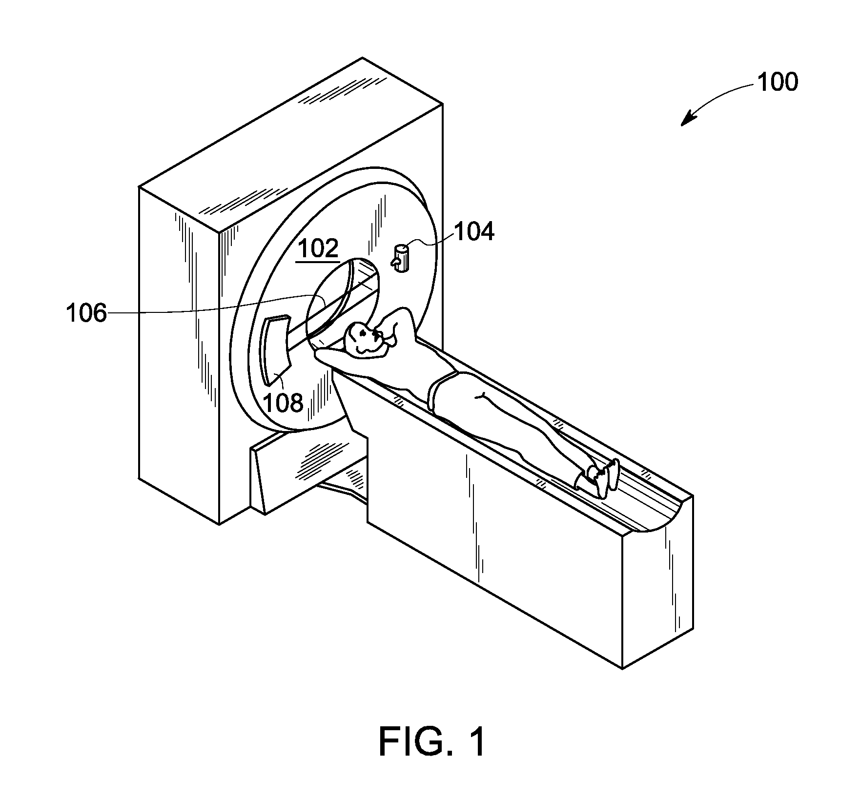
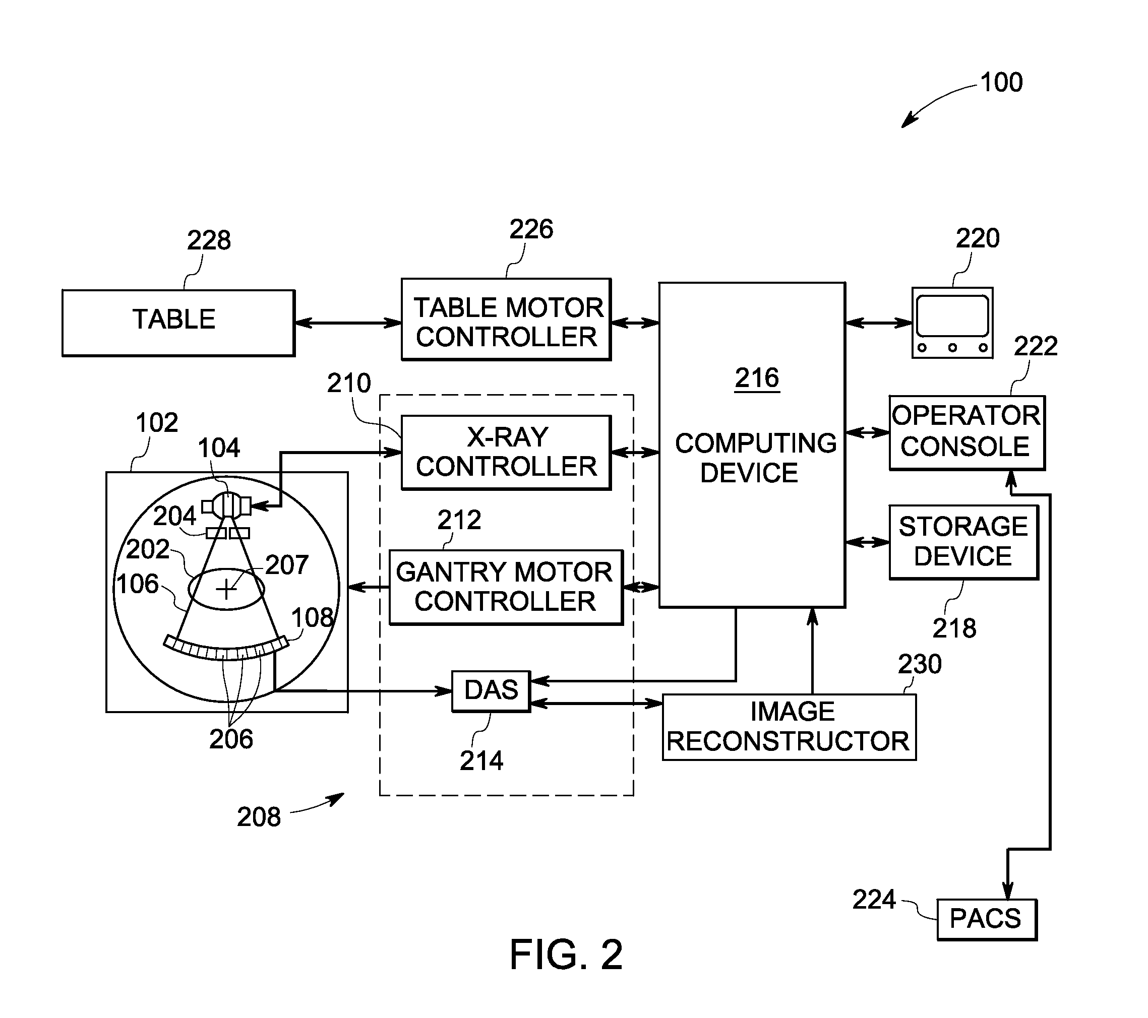
[0016]The following description presents exemplary systems and methods for acquiring sufficient data for reconstruction of a high-resolution image of a targeted region of interest (ROI) of a subject. Particularly, embodiments illustrated hereinafter disclose imaging systems and methods for acquiring image data for enhanced image reconstruction of a targeted ROI. Although exemplary embodiments of the present technique are described in the context of a CT system, it will be appreciated that use of the present technique in various other imaging applications and systems is also contemplated. Some of these systems may include a positron emission tomography (PET)-CT scanner, a single or multiple source imaging system, a single or multiple detector imaging system, a single photon emission computed tomography (SPECT)-CT scanner and / or X-ray tomosynthesis systems.

[0017]Further, in addition to medical imaging, the techniques and configurations discussed herein are applicable in other non-inva...


PUM


Abstract

Embodiments of systems, methods and non-transitory computer readable media for imaging are presented. Preliminary image data corresponding to a first FOV of a subject at a first resolution is acquired using an imaging system including one or more radiation sources and at least one hybrid detector, specifically using at least one section of the hybrid detector having the first resolution. The target ROI is identified using the preliminary image data. Further, the subject is positioned to align the target ROI along a designated axis. Additionally, parameters associated with the sources, the hybrid detector and/or an imaging system gantry are configured for acquiring target image data at a second resolution greater than the first resolution using at least one section of the hybrid detector having the second resolution. Further, one or more images corresponding to at least the target ROI are reconstructed using the target and/or the preliminary image data.

Description

BACKGROUND[0001]Non-invasive imaging techniques are widely used in security screening, quality control, and medical diagnostic systems. Particularly, in medical imaging, non-invasive imaging techniques such as multi-energy imaging allow for unobtrusive, convenient and fast imaging of underlying tissues and organs. To that end, radiographic imaging systems such as nuclear medicine (NM) gamma cameras, computed tomography (CT) systems and positron emission tomography (PET) systems employ a plurality of radiation sources and detectors.[0002]CT systems, for example, typically include an X-ray source and a detector array that may be configured to acquire projection data from different angular positions around the object using a rotatable gantry or by rotating the object. Particularly, the detector array in a CT system employs one or more elements for converting X-ray photon energy into current signals that are integrated over a time period, measured, and ultimately digitized. Certain CT s...

Claims


Application Information

Patent Timeline
Patent Type & Authority Applications(United States)
IPC IPC(8): G01T1/16
CPCA61B6/032A61B6/037A61B6/06A61B6/12A61B6/4021A61B6/4241A61B6/4417A61B6/469A61B6/482A61B6/488G06T11/005
Inventor DEMAN, BRUNO KRISTIAAN BERNARDMILLER, JAMES VRADENBURGJANSEN, FLORIBERTUS P. M. HEUKENSFELDT
Owner GENERAL ELECTRIC CO
Why Eureka
Try Eureka