Exhaust gas treatment apparatus

a technology of exhaust gas treatment and treatment apparatus, which is applied in the direction of lighting and heating apparatus, separation process, and dispersed particle separation, etc., can solve the problems of affecting the efficiency of dust collection, so as to reduce the particle diameter of dust, inhibit the abrasion and blocking of the catalyst layer, and efficiently collect dust

Active Publication Date: 2013-10-31
MITSUBISHI POWER LTD
View PDF1 Cites 5 Cited by
  • Summary
  • Abstract
  • Description
  • Claims
  • Application Information

AI Technical Summary

Benefits of technology

[0019]According to the present invention, it is possible to reduce dust having large particle diameter from an exhaust gas introduced to a catalyst reactor and to inhibit abrasion and blocking of a catalyst layer. The tilt thin plate slit used in the present invention is abrasion-resistant and durable more than conventional mesh screens and wire meshes (metal meshes). Further, a tilt slit structure makes it possible to efficiently collect dust in a hopper of the lower end without being caught in a falling direction. Still further, since it is unnecessary to largely decrease a flow rate of gas introduced to the catalyst layer, a decrease in dust conveyance power can be inhibited and dust deposition in the catalyst layer can be inhibited. In addition, since a dust discharging mechanism is provided, a plant can be operated regardless of cleaning of collected dust upon boiler stop.

Problems solved by technology

Further, when a vertical duct and a hopper in the lower portion thereof are disposed on the upstream side of the NOx removal reactor, it is impossible to sufficiently reduce an exhaust gas flow rate in the duct due to limitations such as plant arrangement.
Also, when it is impossible to assure a sufficient duct length, conveyance of even large dust such as massive ash is not sufficiently inhibited, resulting in massive soot larger than an exhaust gas flow path of a catalyst causing blocking in the catalyst.
On the other hand, when a mesh screen is disposed in a duct, clogging becomes problematic, and also when being disposed in a duct where flow rate is large, the screen itself is abraded, resulting in frequent maintenance operations.
Further, when a mesh screen is disposed in an inlet of the reactor vertically to a gas flow, no discharge mechanism of collected dust is provided and cleaning / discharging is necessary upon boiler stop.
Therefore, it is possible that clogging occurs depending on a frequency of cleaning.

Method used


Image

  • Exhaust gas treatment apparatus
  • Exhaust gas treatment apparatus
  • Exhaust gas treatment apparatus

Examples


Embodiment Construction

[0022]The present invention will now be described in detail with reference to embodiments.

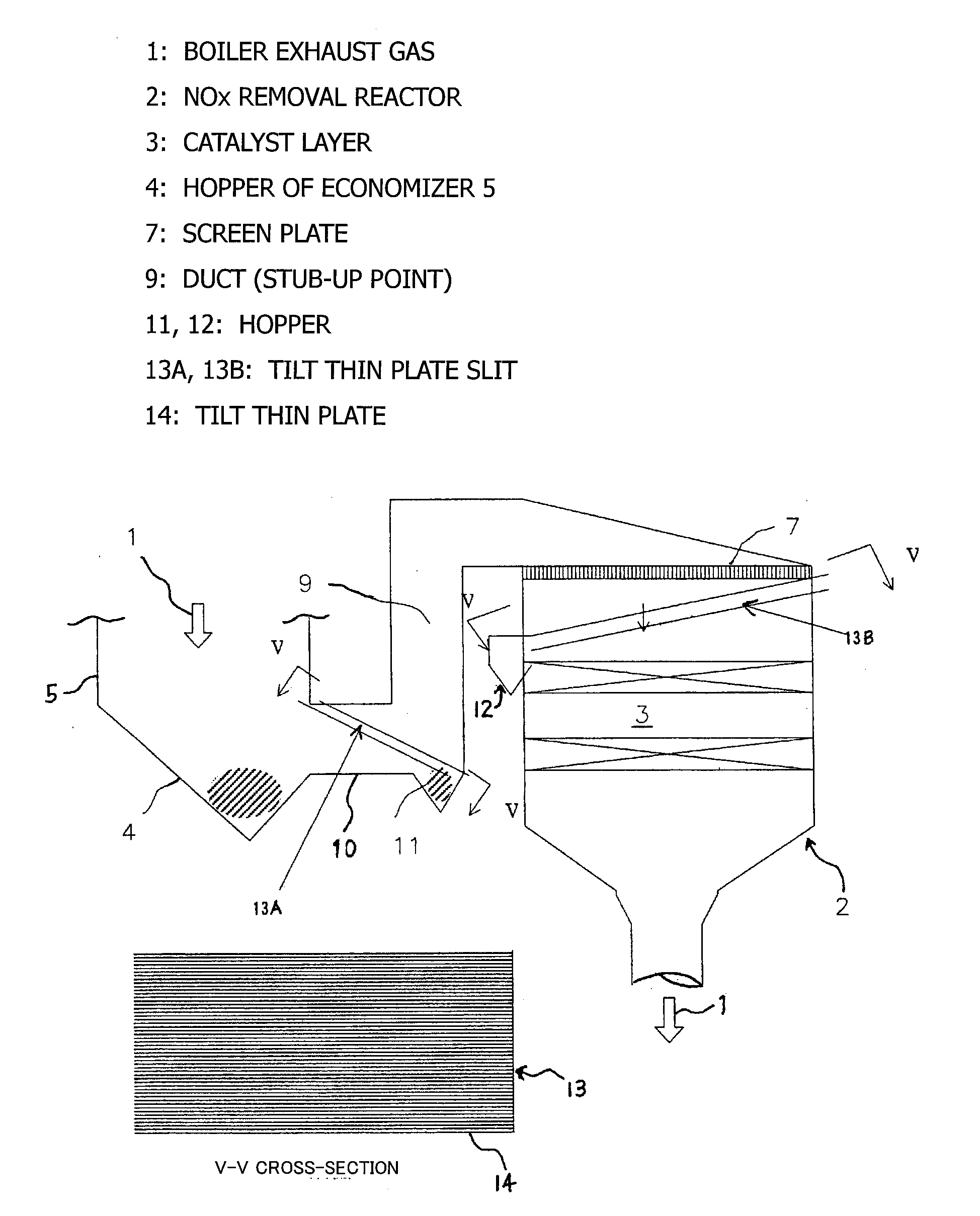
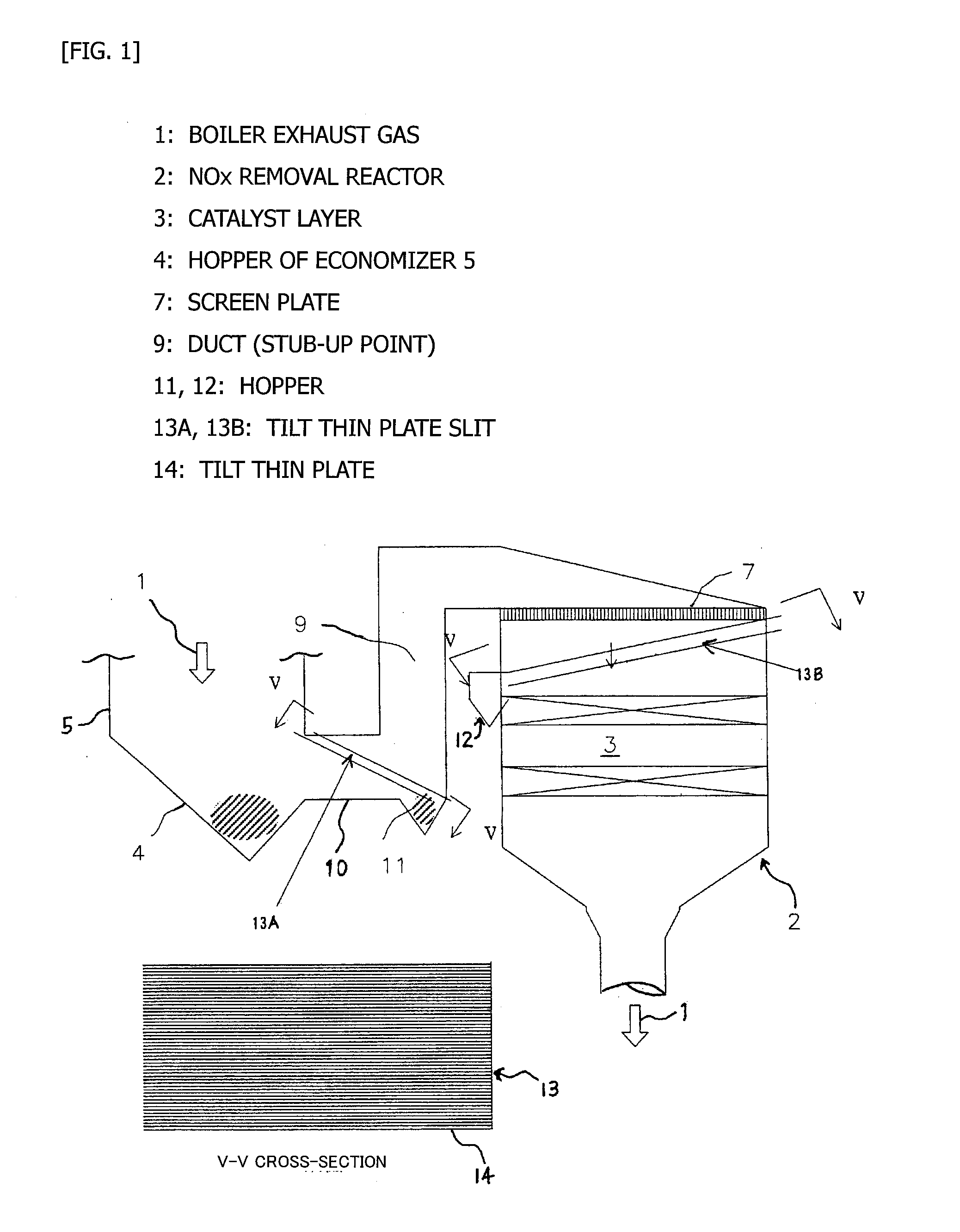
[0023]FIG. 1 is a view illustrating an exhaust gas treatment apparatus representing one embodiment of the present invention. FIG. 2 is a partially schematic view of a tilt thin plate slit used in the present invention. This apparatus comprises a NOx removal reactor 2 having a catalyst layer 3 for removing nitrogen oxides in a combustion exhaust gas 1 discharged from a boiler and the like; and a stub-up point 9 at which a flow of the exhaust gas changes from a horizontal direction to a vertical direction, the stub-up point 9 being disposed in a horizontal duct 10 on the upstream side of an exhaust gas inlet of the NOx removal reactor 2, in which tilt thin plate slits 13A and 13B are provided where a number of thin plates 14 having a long thin diamond shape are disposed in the duct 9 of the horizontal direction of an inlet of the stub-up point 9 and in an inlet of the catalyst layer 3 in the NOx ...


PUM

PropertyMeasurementUnit
opening widthaaaaaaaaaa
heightaaaaaaaaaa
inclination angleaaaaaaaaaa

Abstract

An object of the present invention is to easily reduce dust having large particle diameter that affects blocking and abrasion to prevent deposition thereof in a reactor. An exhaust gas NOx removal apparatus comprises a NOx removal rector having a catalyst layer for removing nitrogen oxides in a combustion exhaust gas; a duct structure having a stab-up point at which a flow of the exhaust gas changes from a horizontal direction to a vertical direction in an exhaust gas duct on the upstream side of the NOx removal reactor; a tilt thin plate slit in which a number of thin plates are disposed in the duct of the horizontal direction of an inlet of the stub-up point or/and in an inlet of the catalyst layer in the NOx removal reactor in a vertical direction with a slit width smaller than an opening width of the catalyst layer at a predetermined inclination angle relative to the cross-section of an exhaust gas flow path; and a dust collecting/discharging portion attached to the lower end of a tilt thin plate slit.

Description

TECHNICAL FIELD[0001]The present invention relates to an exhaust gas treatment apparatus, and particularly to an exhaust gas treatment apparatus for a system carrying out dry denitration of an exhaust gas containing dust using ammonia and a catalyst.BACKGROUND ART[0002]As a method for removing nitrogen oxides in an exhaust gas, conventionally, a method of selective reduction with ammonia using a catalyst has been mainstream. As an apparatus therefor, there is being used an apparatus for denitration reaction, in which ammonia serving as a reducing agent is introduced, together with an exhaust gas, into a reactor packed with a catalyst layer having NOx removal activity and a flow path parallel to the exhaust gas.[0003]When dust is contained in an exhaust gas as seen in coal-fired power generation, an electric dust collector or a bag filter is generally disposed on the downstream side of a NOx removal apparatus and an air preheater for dust removal, or an electric dust collector is dis...

Claims


Application Information

Patent Timeline
Patent Type & Authority Applications(United States)
IPC IPC(8): B01D53/94
CPCB01D53/9418B01D53/8631B01D2258/0283B03C3/017F23J15/02F23J2217/20B01D53/56B01D53/86B01D53/90B01D53/94
Inventor ISHIKAWA, KANJIISHIOKA, MASAAKIYASHIRO, KATSUHIRO
Owner MITSUBISHI POWER LTD
Why Eureka
Try Eureka