Electrical Converter

a technology of electric converters and converters, applied in the direction of electrical device casings/cabinets/drawers, electric devices, structural associations, etc., can solve problems such as electromagnetic noise, and achieve the effect of reducing radiated noise, being inexpensive and small, and being convenient to us

Active Publication Date: 2013-11-07
HITACHI ASTEMO LTD
View PDF9 Cites 51 Cited by
  • Summary
  • Abstract
  • Description
  • Claims
  • Application Information

AI Technical Summary

Benefits of technology

[0011]The present invention can provide an inexpensive and small electrical converter that

Problems solved by technology

When the switching elements switch a direct-current power supply fast, surge current and voltage are

Method used


Image

  • Electrical Converter
  • Electrical Converter
  • Electrical Converter

Examples


second embodiment

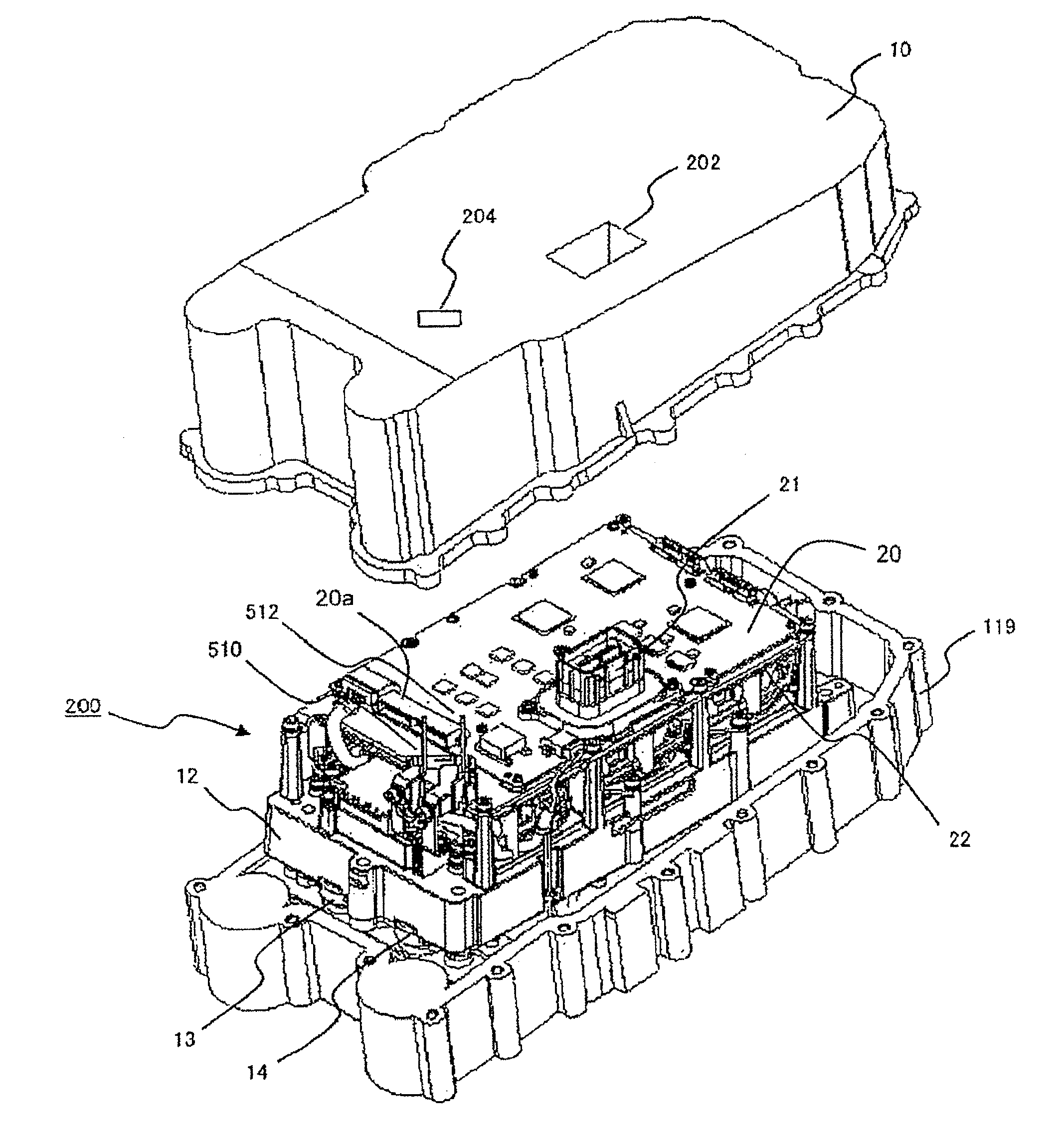
[0152]FIG. 21 is a diagram showing an example of a cross-sectional view of an electrical converter according to the present invention.

[0153]The electrical converter according to the second embodiment of the present invention is characterized in that a general radio wave absorbent 11b made of carbon, ferrite, or the like is used to surround the battery negative electrode-side connection terminal section 510 and the battery positive electrode-side connection terminal section 512. As a result, induced current induced from the battery negative electrode-side connection terminal section 510 and the battery positive electrode-side connection terminal section 512 to the control connector 20a can be reduced, and secondary radiation from the walls 11a can be prevented.

third embodiment

[0154]FIG. 22 is a diagram showing an example of a cross-sectional view of an electrical converter according to the present invention.

[0155]The electrical converter according to the second embodiment of the present invention is characterized in that a dielectric material 11c with a higher dielectric constant than air is inserted between the battery negative electrode-side connection terminal section 510, the battery positive electrode-side connection terminal section 512 and the wall 11a electrically connected to the base plate 11. The battery (direct current) negative electrode-side connection terminal section 510, the battery (direct current) positive electrode-side connection terminal section 512 and the wall 11a electrically connected to the base plate 11 are closely arranged, and by inserting the high-dielectric material 11c to the spaces, the noise current that entered the battery negative electrode-side connection terminal section 510 and the battery positive electrode-side c...

fourth embodiment

[0156]FIG. 23 is a diagram showing an example of a cross-sectional view of an electrical converter according to the present invention.

[0157]The electrical converter according to the second embodiment of the present invention is characterized in that the walls 11a are formed as portions of the case 10.

[0158]When the case 10 is grounded from above the base plate 11, the walls 11a may be formed as portions of the case 10 as shown in FIG. 23. As a result, the inductance of the walls 11a up to the ground is reduced, and since the walls 11a are installed at points where the potential is stable, the noise reduction effect can be increased.

[0159]Since, in the present embodiment, the targets to be cooled by the refrigerant flowing through the channel 19 are mainly the drive power modules 300 and 301, the power modules 300 and 301 are stored in the channel 19 and cooled by direct contact with the refrigerant. Meanwhile, cooling of the auxiliary machine power module 350 is also demanded, altho...


PUM


Abstract

Radiated noise caused by switching noise of power semiconductor elements in an electrical converter is reduced. The electrical converter is characterized in comprising: a case; a power module mounted on the case and comprising a plurality of power semiconductor elements; a metal plate mounted to the power module and fixed to the case; a control circuit board arranged on the metal plate, for controlling the power semiconductor elements; and a direct-current input terminal electrically connected to a battery. The electrical converter is also characterized in being provided at the bottom with a transmission or motor, and at the top with a connector for connecting the battery and the direct-current input terminal. The electrical converter is further characterized in that the metal plate is curved, and a portion of the curved metal plate is arranged in the space between the control circuit board and the direct-current input terminal.

Description

TECHNICAL FIELD[0001]The present invention relates to an electrical converter.BACKGROUND ART[0002]An electrical converter such as an inverter that generates alternating-current power from direct-current power of a battery or the like includes: a main circuit including switching elements; a drive circuit that drives the switching elements; a smoothing capacitor; and a control circuit that generates an operating signal to be transmitted to the drive circuit or the like.[0003]When the switching elements switch a direct-current power supply fast, surge current and voltage are generated along with rapid change in the voltage and current, and this causes electromagnetic noise. In general, to prevent the influence of the switching noise of power semiconductor elements, a shielding member is disposed between a bus bar as a noise source and a control circuit board. An example of a structure for solving such as problem includes Patent Literature 1 (JP-A-2008-125240) providing “a power convert...

Claims


Application Information

Patent Timeline
IPC IPC(8): H05K5/00B60L50/15B60L50/16
CPCH05K5/0026H02M1/44H02M7/003B60L1/003B60L3/003B60L15/20B60L2200/10B60L2200/32B60L2200/36B60L2210/40B60L2240/36B60L2240/423B60L2200/26H02K11/0094H02K11/33B60L50/61B60L50/16Y02T10/62Y02T10/64Y02T10/70Y02T10/72Y02T10/7072H05K7/14322H05K7/1432
Inventor FUKUMASU, KEISUKETORIGOE, MAKOTONAKAJIMA, KENICHIROTAKAHASHI, MASAYOSHIFUNATO, HIROKI
Owner HITACHI ASTEMO LTD
Why Eureka
Try Eureka