
Method for operating a soot sensor

a sensor and carbon particulate technology, applied in the direction of electric control, instruments, machines/engines, etc., can solve the problems of high carbon particulate emission of optimized otto engines, limited fossil energy carrier availability, and extreme carcinogenicity of carbon particulates, etc., to achieve simple and precise manner, easy monitoring, and long life

Inactive Publication Date: 2013-11-14
CONTINENTAL AUTOMOTIVE GMBH
View PDF29 Cites 19 Cited by
  • Summary
  • Abstract
  • Description
  • Claims
  • Application Information

AI Technical Summary

Benefits of technology

The invention is a method for measuring carbon particles in the exhaust gas of vehicles using a carbon particulate sensor. The sensor has a short downtime and can measure the carbon concentration almost continuously. This helps to reduce emissions of pollutants. The sensor's electrodes are made using thick-layer technology or co-fired technology, which makes them durable and cost-effective. The thick-layer electrodes have a long life. The sensor can also be easily monitored and terminated during its burning-off process using an electrical heating element.

Problems solved by technology

These discussions are associated with the fact that the availability of fossil energy carriers is limited.
However, the disadvantage of this combustion engineering in comparison to optimized Otto engines is a considerably higher emission of carbon particulates.
Carbon particulates can be extremely carcinogenic particularly as a result of the concentration of polycyclic aromatic hydrocarbons and various regulations have already been introduced in response to this.
This method is suitable for costly measuring devices.
However, when attempts are made to also use this method as a mobile sensor system in the exhaust gas tract, it has been established that approaches of this type for providing a sensor in a motor vehicle are encumbered by high costs as a result of the expensive optical structure.
Furthermore, the problems relating to the necessary optical windows being contaminated by combustion gases have not yet been solved.
However, the technical aspect of arranging these particulates is extremely difficult and costly.

Method used


Image

  • Method for operating a soot sensor
  • Method for operating a soot sensor
  • Method for operating a soot sensor

Examples


Embodiment Construction

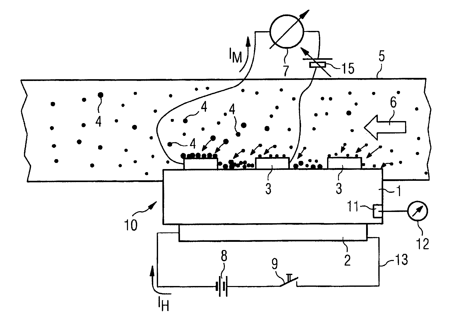
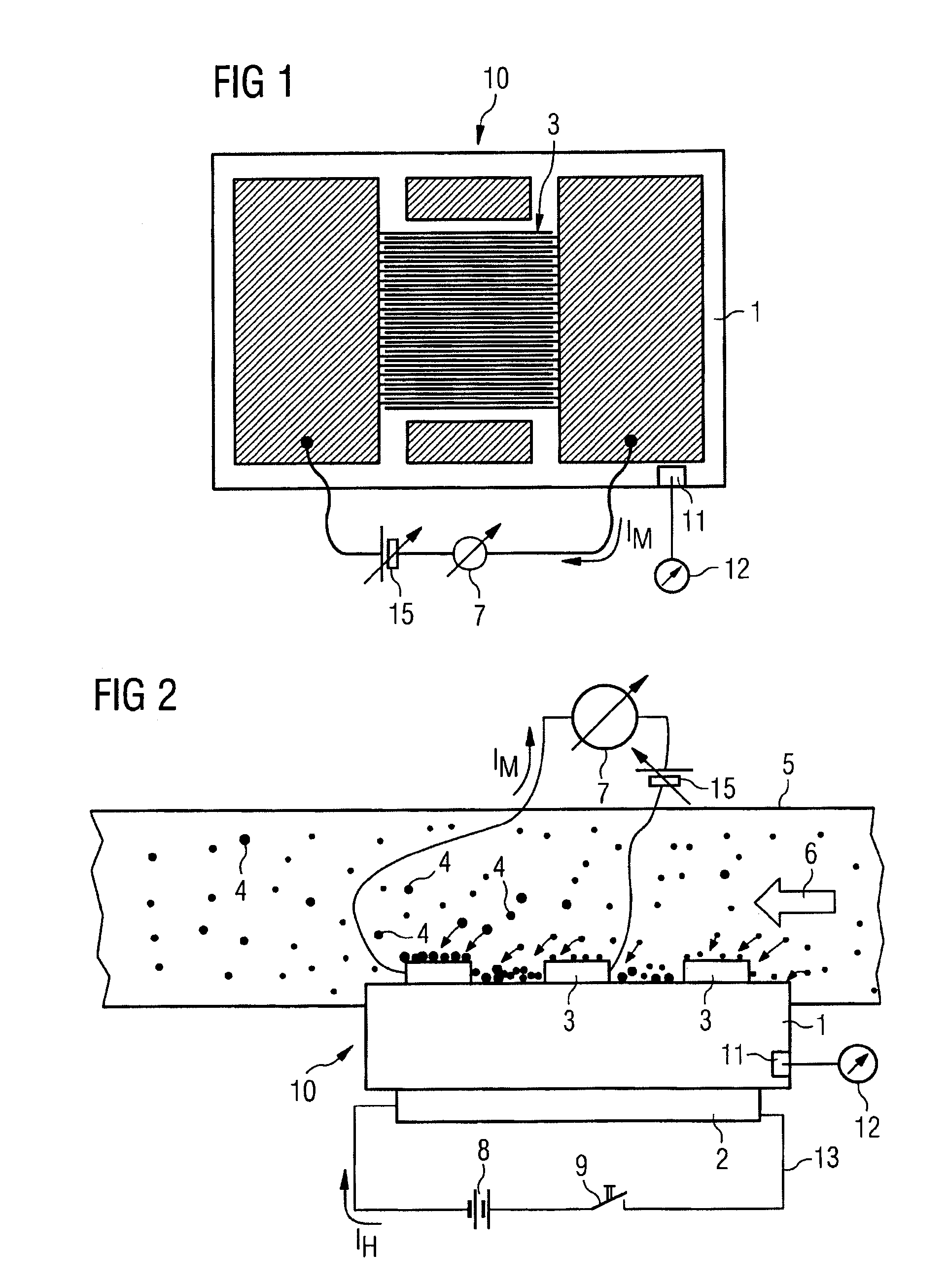
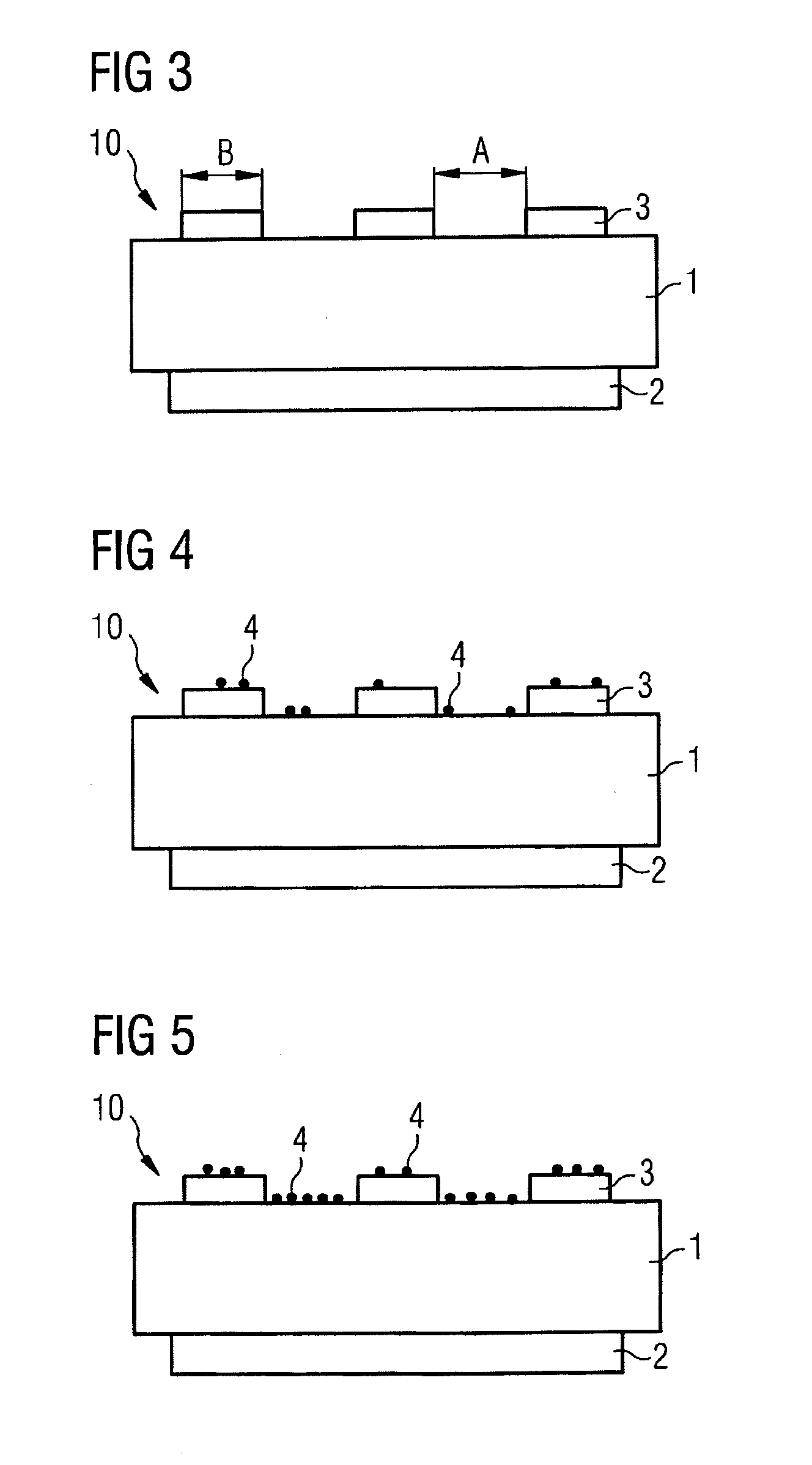
[0027]FIG. 1 illustrates a carbon particulate sensor 10 that has a molded body 1, a heating element, not represented here, and a structure of measuring electrodes 3 that engage one with the other in an interleaved finger manner. The molded body 1 can be produced from a ceramic material or can be embodied from a different material that comprises electrically insulating properties and resists the temperatures involved when burning-off carbon particulates 4. In order to burn off the carbon particulates 4 from the carbon particulate sensor 10, the carbon particulate sensor 10 is heated to temperatures between 500 and 800° C. in a typical manner with the aid of an electrical resistance heater 4. The electrically insulating molded body 1 must be able to withstand these temperatures without being damaged. The structure of the measuring electrodes 3 is embodied in this case by way of example as a mesh-like structure that is also described as an interleaved finger electrode structure wherein...


PUM


Abstract

A method for operating a soot sensor that has an interdigital electrode structure, to which a measurement voltage is applied. Soot particles from an exhaust gas flow are deposited onto the interdigital electrode structure and the measurement current is evaluated as a measure of the soot load of the soot sensor. The interdigital electrode structure is burned clean at or above a predetermined soot load, which is detected by means of an upper current threshold. The method includes burning the interdigital electrode structure clean by heating up the soot sensor after the upper current threshold has been reached; monitoring the measurement current while the interdigital electrode structure is being burned clean; and stopping the burning clean when the value of the measurement current has reached a lower current threshold.

Description

CROSS REFERENCE TO RELATED APPLICATION[0001]This is a U.S. national stage of application No. PCT / EP2011 / 073517, filed on Dec. 21, 2011. Priority is claimed on German Application No. DE 10 2010 055 478.2 filed Dec. 22, 2010, the content of which is incorporated here by reference.BACKGROUND OF THE INVENTION[0002]1. Field of the Invention[0003]The invention relates to a method for operating a carbon particulate sensor, wherein the carbon particulate sensor comprises an interleaved finger electrode structure to which a measuring voltage is applied, wherein carbon particulates from an exhaust gas flow are deposited on the interleaved finger electrode structure and the measuring current that flows over the carbon particulates and the interleaved finger electrode structure is evaluated as a measurement for the carbon particulate concentration on the carbon particulate sensor and wherein the interleaved finger electrode structure is burned clean if the carbon particulate concentration that ...

Claims


Application Information

Patent Timeline
IPC IPC(8): G01N15/06
CPCG01N15/0656F01N9/002F01N2560/05F01N2560/20F02D41/1466F02D41/1494
Inventor ANTE, JOHANNESGRASS, PHILIPPEHERRMANN, MARKUSREITMEIER, WILLIBALDSCHADLICH, DENNYWEIGL, MANFREDWILDGEN, ANDREAS
Owner CONTINENTAL AUTOMOTIVE GMBH
Learn More