Variable speed compressor and control system

a compressor and variable speed technology, applied in the direction of pump control, non-positive displacement fluid engine, climate sustainability, etc., can solve the problems of low boost ratio and insufficient flow to provide desired engine torque, and achieve the effect of fully controllable boost-on-demand air compression operation

Inactive Publication Date: 2013-11-14
THE TIMKEN CO
View PDF8 Cites 9 Cited by
  • Summary
  • Abstract
  • Description
  • Claims
  • Application Information

AI Technical Summary

Benefits of technology

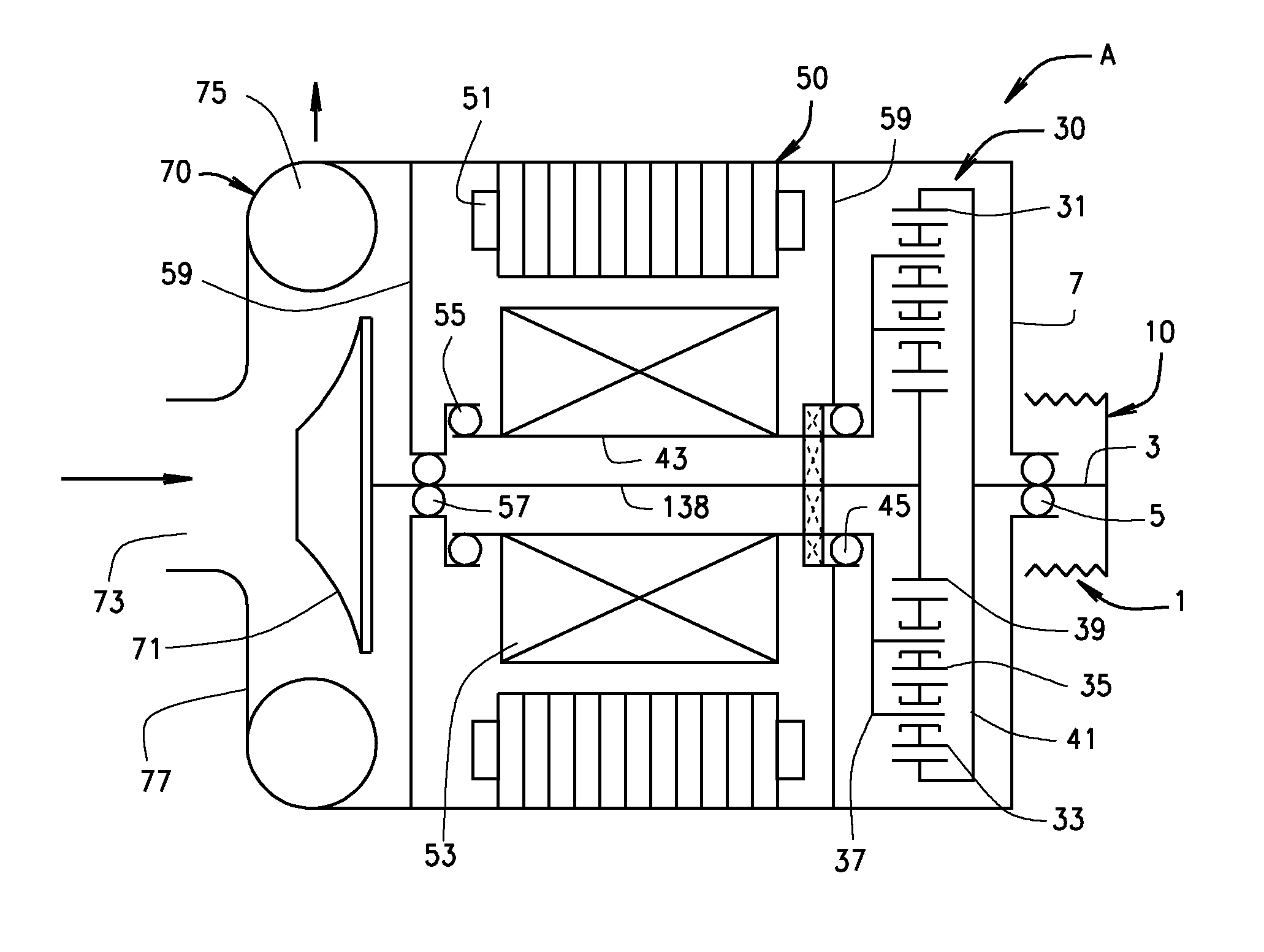
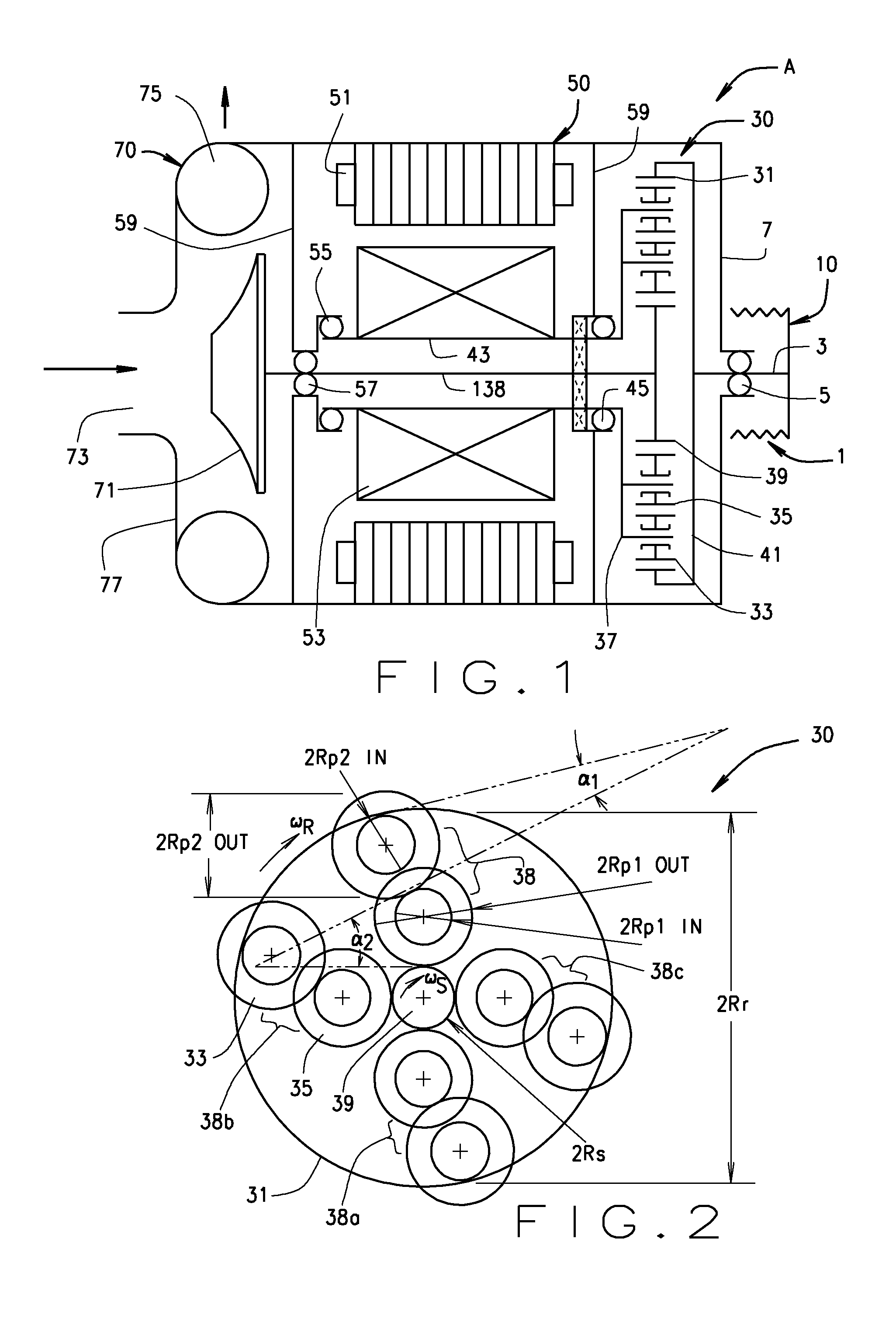
[0008]Briefly stated, the present disclosure provides a variable speed compressor system along with an associated control system and structure. The variable speed compressor system incorporates electric power generation and storage capability by combining the compressor with an alternator in a compact unit for connection to an external battery or other energy storage device. The control system and structure facilitates fully controllable boost-on-demand air compression operation across entire engine speed range and offers intelligent electric power generation, such as is required to maintain a battery's state of charging (SOC).
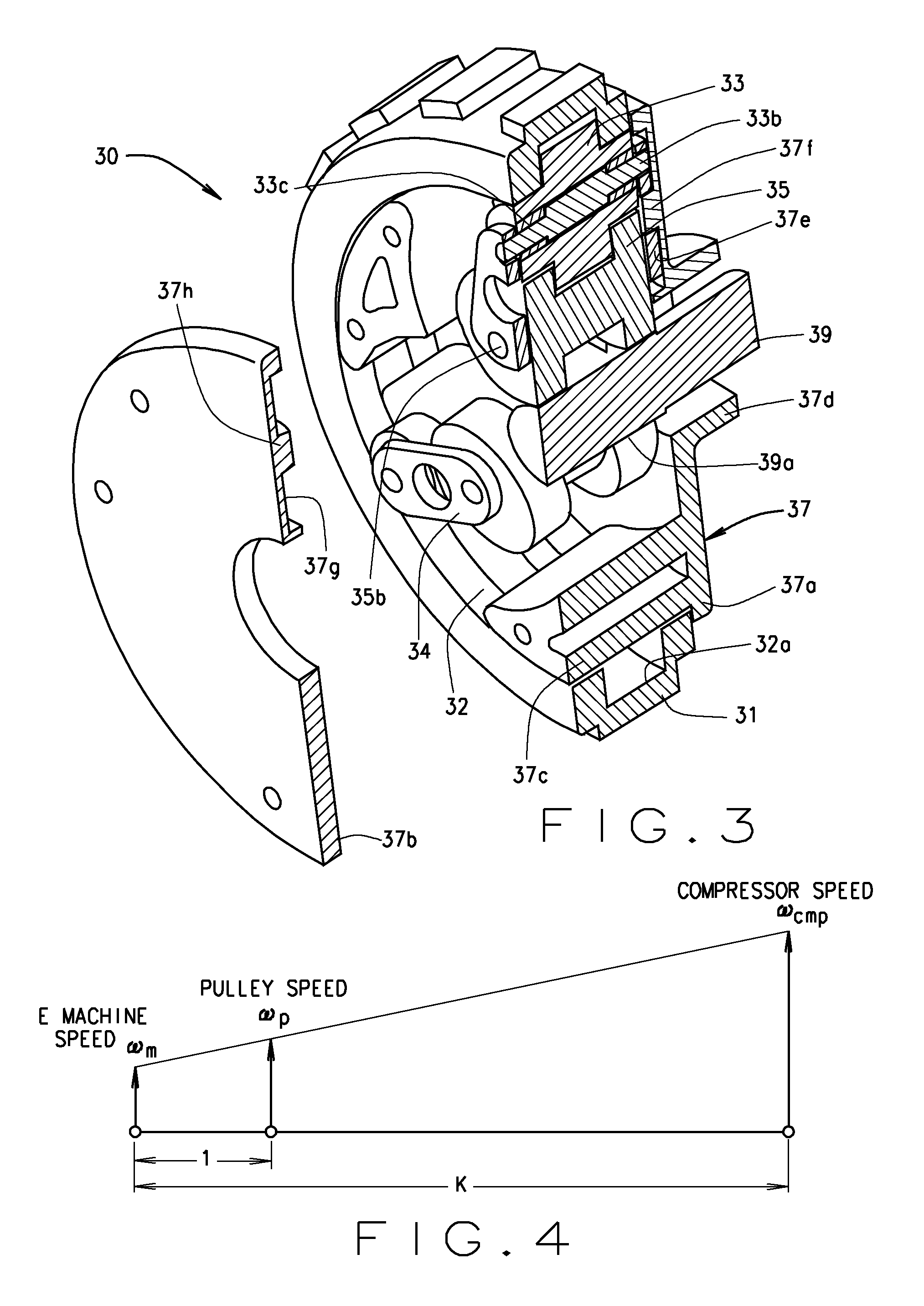
[0011]The first controlled mode of operation is the boosting mode, where the electric machine is controlled to rotate in an opposite direction relative to the direction of rotation of the drive pulley. The electric machine is in a motoring state, applying shaft torque in the same direction as the speed of rotation. The electric machine draws electric power from an external battery or energy storage system and delivers it to the three-shaft system providing drive power and shaft torque. The three-shaft drive system then combines the drive power with mechanical power from drive pulley and delivers the power to the supercharger compressor. In the boosting mode, the three-shaft drive system provides an increased speed ratio between the supercharger compressor and drive pulley. Therefore, even at relatively low engine speeds, the supercharger compressor is able to operate at a higher speed to provide high pressure forced air induction and to boost engine torque and power as required.
[0014]The three operating modes are realized under a so-called speed control logic by the control system where the control objective is to achieve a desired speed of the variable-speed compressor or electric machine by controlling the shaft torque of the electric machine through a torque-based control structure. The control structure comprises at least one feedback loop which compares the measured or estimated speed of the compressor shaft to a reference speed of the compressor shaft and generates a drive torque command for the electric machine. The feedback loop includes a PID control unit whose gains are determined by, among others, the rotational momentums of system components. The torque-based control structure may further include a feed-forward loop to improve controllability. The feed-forward loop generates a base drive torque command for the electric machine based on the operation status of the variable-speed compressor. Under the base torque command, the variable speed compressor is able to maintain substantial torque equilibrium among the three shafts in the three-shaft drive system under steady state conditions.

Problems solved by technology

At low engine speed, the boost ratio is low; the in-take mass flow is insufficient to provide desired engine torque.

Method used


Image

  • Variable speed compressor and control system
  • Variable speed compressor and control system
  • Variable speed compressor and control system

Examples


Embodiment Construction

[0027]The following detailed description illustrates the invention by way of example and not by way of limitation. The description enables one skilled in the art to make and use the present disclosure, and describes several embodiments, adaptations, variations, alternatives, and uses of the present disclosure, including what is presently believed to be the best mode of carrying out the present disclosure.

[0028]While the compressor system of the present disclosure is described below in the exemplary embodiment in the context of a variable speed supercharger, those of ordinary skill in the art will recognize that the control system and features of the present disclosure may be utilizes with other types of variable speed compressor systems, such as turbochargers or turbines, and that such systems are considered to be within the scope of the present disclosure. In addition, while the engine of the present disclosure is described below in the exemplary embodiments as being an internal co...


PUM


Abstract

A variable speed compressor system (A) incorporating an electric power generation capability by combining a variable-speed compressor assembly (70) with an electric motor assembly (50) via a drive subassembly (30) in a compact unit regulated by a control system (400). The control system (400) facilitates fully controllable boost-on-demand forced-air induction operation across an entire engine speed range, and offers intelligent electric power generation.

Description

CROSS-REFERENCE TO RELATED APPLICATIONS[0001]The present application is related to, and claims priority from, U.S. Provisional Patent Application Ser. No. 61 / 436,738 filed on Jan. 27, 2011, which is herein incorporated by reference.STATEMENT REGARDING FEDERALLY SPONSORED RESEARCH[0002]Not Applicable.BACKGROUND OF THE INVENTION[0003]The invention is related generally to a variable speed compressor system, and in particular, to a variable speed compressor and alternator in a compact unit coupled to an engine, with a related control structure to provide fully controllable boost-on-demand supercharging operation across an entire engine speed range together with intelligent electric power generation.[0004]The increasing demand for fuel efficiency and emission reduction requires engines to provide higher output without increasing total piston displacement and weight. An effective way to achieve this goal is the use of forced air induction or compressor systems to boost the intake pressure...

Claims


Application Information

Patent Timeline
Patent Type & Authority Applications(United States)
IPC IPC(8): F02B39/10
CPCF02B39/10F02B33/40F02B39/04F02B39/06F04D25/028F04D27/0261Y02B30/70
Inventor AI, XIAOLAN
Owner THE TIMKEN CO
Why Eureka
Try Eureka