
Solid organic scintillator doped by one or more chemical elements

a technology of organic scintillators and chemical elements, applied in the direction of conversion screens, nuclear engineering, luminescent compositions, etc., can solve the problems of poor quality, little useful for x-imaging, and x-ray images obtained with materials

Active Publication Date: 2013-11-14
COMMISSARIAT A LENERGIE ATOMIQUE ET AUX ENERGIES ALTERNATIVES
View PDF3 Cites 6 Cited by
  • Summary
  • Abstract
  • Description
  • Claims
  • Application Information

AI Technical Summary

Benefits of technology

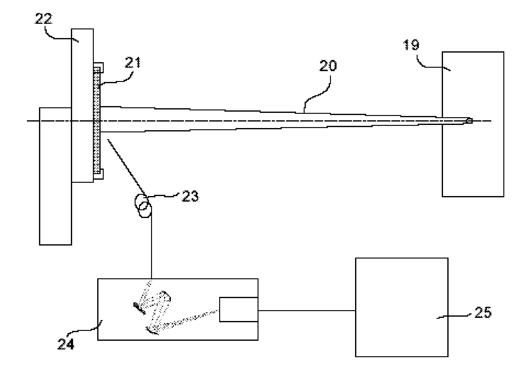
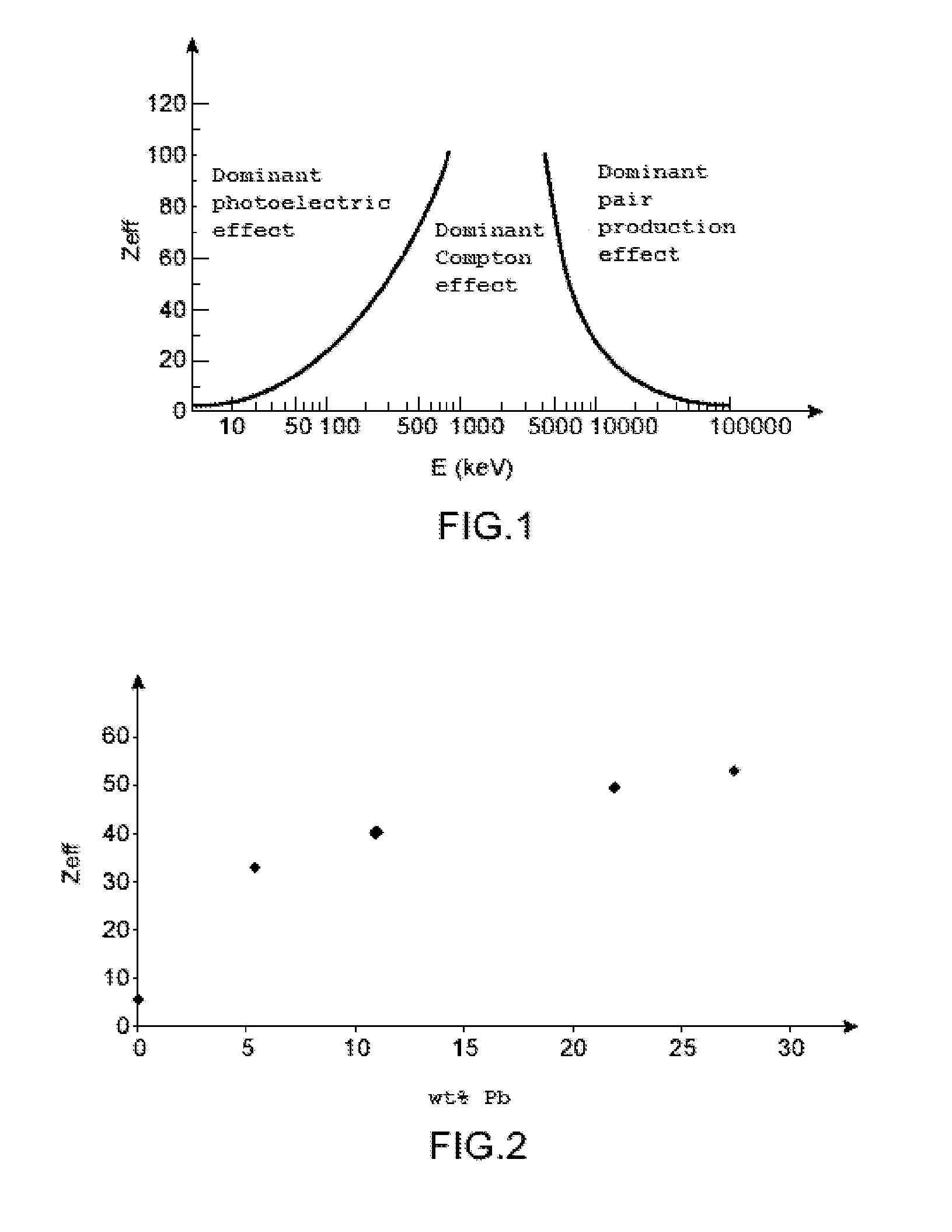
The invention is about scintillators, which are used to detect radiation. These scintillators have several advantages. When a chemical element like lead is added to the scintillator, it increases the atomic number (a measure of the size of the element) of the material. This makes the scintillator more effective at detecting radiation. The patent text shows that increasing the lead content in the scintillator results in higher atomic number. This provides a way to make these scintillators better at their job of detecting radiation.

Problems solved by technology

Therefore the X-ray images obtained with materials which, after interaction with incident X photons generate a Compton effect, are of poor quality since the X photons diffusing in the material are not completely absorbed by the material or, if they are absorbed, may be absorbed in such manner that they contribute to obtaining a blurred image.
On the other hand, the solid organic scintillators conventionally used (typically having an effective atomic number Zeff in the order of 5) do not allow complete absorption of X-rays of energy ranging from 10 to 40 keV, which means that they are little useful for X-imaging.
To meet these three conditions (namely, a scintillator having a high effective atomic number, a scintillator emitting fluorescence light of long wavelength and a scintillator advantageously having a short scintillation decay time), inorganic scintillators have been proposed but unconvincingly for X-ray imaging dedicated to Megajoule Laser experiments.
Additionally, most of these scintillators are hygroscopic, which limits their field of application, in particular for X-ray imaging.

Method used


Image

  • Solid organic scintillator doped by one or more chemical elements
  • Solid organic scintillator doped by one or more chemical elements
  • Solid organic scintillator doped by one or more chemical elements

Examples


example 1

Preparation of a Scintillator Conforming to the Invention

[0123]The scintillator conforming to the invention prepared according to this Example comprises a polymeric matrix formed of a poly(vinyltoluene-co-methacrylic acid) copolymer cross-linked with lead dimethacrylate, in which a first fluorophore compound is dispersed: N-(2′,5′-di-t-butylphenyl)-4-butylamino-1,8-naphthalimide of following formula (II):

[0124]and a second fluorophore compound: (bis-N-( 2,5-di-t-butylphenyl)-3,4,9,10-perylenetetracarbodiimide) of following formula (IV):

[0125]Initially, preparation of the first fluorophore compound is performed after which the scintillator as such is prepared.

[0126]The second fluorophore compound is commercially available.

a) Preparation of N-(2′,5′-di-t-butylphenyl)-4-butylamino-1,8-naphthalimide

[0127]The title compound is prepared as per the following reaction scheme:

Ac meaning acetyl and NMP meaning N-methylpyrrolidone.

[0128]Compounds 1 and 2 are commercially available.

*Synthesis o...

example 2

Preparation of Another Scintillator Conforming to the Invention

[0147]The scintillator conforming to the invention prepared in this Example comprises a polymeric matrix formed of a poly(2-hydroxyethyl methacrylate) polymer cross-linked with lead dimethacrylate, in which are dispersed a first fluorophore compound: N-(2′,5′-di-t-butylphenyl)-4-butylamino-1,8-naphthalimide of following formula (II):

[0148]and a second fluorophore compound: (bis-N-( 2,5-di-t-butylphenyl)-3,4,9,10-perylenetetracarbodiimide) of following formula:

[0149]The first fluorophore compound is prepared following the operating protocol described in Example 1.

[0150]The second fluorophore compound is commercially available.

[0151]The scintillator as such is prepared as per the following operating protocol.

[0152]Pure 2-hydroxyethyl methacrylate (5 g, 38.4 mmol), lead dimethacrylate (5 g, 13.2 mmol), N-( 2′,5′-di-t-butylphenyl)-4-butylamino-1,8-naphthalimide (5 mg, 0.011 mmol) and bis-N-(2,5-di-t-butylphenyl)-3,4,9,10-per...

example 3

[0163]The scintillator conforming to the invention prepared in accordance with this Example comprises a polymeric matrix comprising a poly(vinyltoluene-co-methacrylic acid) copolymer cross-linked with n-dibutyltin dimethacrylate in which are dispersed a first fluorophore compound: N-(2′,5′-di-t-butylphenyl)-4-butylamino-1,8-naphthalimide of following formula (II):

[0164]and a second fluorophore compound: (bis-N-( 2,5-di-t-butylphenyl)-3,4,9,10-perylenetetracarbodiimide) of following formula (IV):

[0165]Initially the first fluorophore compound is prepared followed by the preparation of the scintillator as such.

[0166]The second fluorophore compound is commercially available.

[0167]The scintillator as such is prepared as per the following operating protocol.

[0168]Pure methacrylic acid (2.525 g, 29.3 mmol), pure vinyltoluene (2.525 g, 21.4 mmol), n-dibutyltin dimethacrylate (3.367 g, 8.3 mmol), N-(2′,5′-di-t-butylphenyl)-4-butylamino-1,8-naphthalimide (4.2 mg, 0.01 mmol) and bis-N-(2,5-di-...


PUM


Abstract

The invention relates to a solid organic scintillator comprising a polymeric matrix in which there are dispersed one or more fluorophore compounds and one or more chemical elements having an atomic number ranging from 40 to 83, characterized in that said scintillator has a weight content of said chemical elements of at least 5% by weight relative to the total weight of the scintillator, and in that the scintillator emits an emission spectrum comprising an emission peak at a wavelength of at least 550 nm.

Description

TECHNICAL FIELD[0001]The present invention pertains to solid organic scintillators doped by one or more chemical elements comprising a specific polymeric matrix in which fluorophore compounds are dispersed, these scintillators having the combination of following characteristics:[0002]possible high doping level of chemical element(s);[0003]capability of emitting at long wavelengths (in particular at wavelengths of at least 550 nm); and[0004]optionally, a short scintillation decay time.[0005]The invention finds particular application in:[0006]the medical field, more particularly medical imaging using X-rays;[0007]the field of experimental physics, and more particularly the design of X-ray diagnostic imaging for Megajoule Laser plasma experiments.STATE OF THE PRIOR ART[0008]Conventionally a scintillator is intended for the detection of radiation or of high energy particles, which requires the use of material capable of using radiation-matter interaction to convert the energy of ionizin...

Claims


Application Information

Patent Timeline
IPC IPC(8): C09K11/06
CPCC09K11/06C09K2211/1007C09K2211/1029C09K2211/1033C09K2211/1044G21K4/00
Inventor HAMEL, MATTHIEUDARBON, STEPHANENORMAND, STEPHANETURK, GREGORY
Owner COMMISSARIAT A LENERGIE ATOMIQUE ET AUX ENERGIES ALTERNATIVES
Learn More