Method and Apparatus for Monitoring Timing of Critical Paths

a technology of critical path and monitoring method, applied in the direction of instruments, specific program execution arrangements, program control, etc., can solve the problems of path failure first, erroneous operation, and path failure, and achieve the effect of reducing the drawbacks of existing systems

Inactive Publication Date: 2013-11-14
STICHTING IMEC NEDERLAND
View PDF1 Cites 26 Cited by
  • Summary
  • Abstract
  • Description
  • Claims
  • Application Information

AI Technical Summary

Benefits of technology

[0012]The present disclosure seeks to provide a more reliable technique of detecting and preventing functional failures in a digital design in modern technologies operating at low power, more specifically, providing automated integration and dynamic tracking of variations such as, for example, process, voltage and temperature variations whilst mitigating the drawbacks of existing systems.
[0017]Determining a probability of failure by counting the critical timing events exploits dynamic on-chip variation, e.g., supply and temperature variation (externally or internally due to different processing) and clock jitter. This fuzzy measure allows very precise fine-tuning of the margin as opposed to a classical binary 1 / 0 feedback of canary circuits. As a result, more reliable detection of the extreme frequency-voltage combination of a chip is achieved before it actually fails, so the system is able to react appropriately to prevent the failure actually occurring. Moreover, the methodology can be easily integrated in the design flow and scalable across technologies.
[0023]The apparatus may further comprise an enable / disable terminal for enabling or disabling any one of the plurality of canary circuits to minimize the impact on functional design in terms of power and noise coupling.

Problems solved by technology

Enabling systems to run at multiple frequency and voltage levels is a challenging process and requires characterization of the processor to ensure its correct operation at the required operating points.
For example, if the frequency is too high (i.e. the logic between the two sequential elements is too slow for the given frequency) the data signal will arrive too late on the input of the next (also referred as receiving) sequential element to be captured properly resulting in erroneous operation.
This problem is called a setup timing violation.
Even when designed to meet (easily) the timing requirements, these paths will fail first, for example, when the design is in a (very) slow process corner or when dynamic frequency and voltage scaling is applied (DVFS).
As modern technologies (such as 40 nm and below) designs suffer from high process variability, which are worsened when operating at reduced supply voltages, for marginal voltage-frequency combinations some chips will work, others (with slower devices) will not.
However, the canary circuits require significant voltage safety margins (adding up to 50% of the total energy budget) to guarantee computational correctness at the worst case combination of intra-die process variations, and local fluctuations in voltage and temperature, leading to a loss in energy efficiency.
Further, they also have difficulty responding to rapidly changing conditions.
However, these approaches cannot compensate for mismatches in tracking across PVT between the actual critical path and the modelled paths, die variations between location of monitor path and critical path, random variations between monitor path and critical path, response times of monitor circuit on fast changing conditions, aging (at different rate), and therefore require additional safety margins to the critical voltage.
However, this technique does not offer a good trade-off between the overhead due to re-computation and saved energy.
Further, since the error correction hardware is part of the circuitry (sequential elements), its area and power footprint is increased.
However, this approach has proved to be problematic in observing all potentially functional failing flops.
The duplicates have an increased delay on the data, thereby making it more timing critical.
However, the tracking of random variation is limited to the duplicated storage elements.
Since, scaling down of the voltage is based on the first signalling event only, this approach is prone to errors, and for signalling rates in the order of seconds, this approach would be unsuitable for dynamic tracking.

Method used


Image

  • Method and Apparatus for Monitoring Timing of Critical Paths
  • Method and Apparatus for Monitoring Timing of Critical Paths
  • Method and Apparatus for Monitoring Timing of Critical Paths

Examples


Embodiment Construction

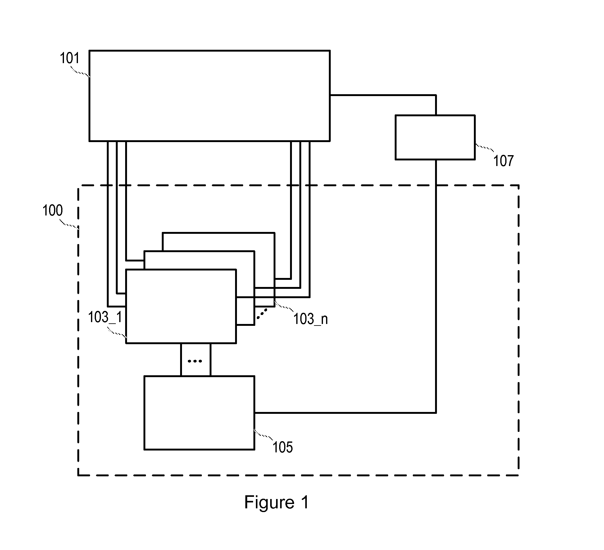
[0035]With reference to FIGS. 1, 2a and 2b, apparatus 100 for monitoring timing of a plurality of critical paths of a functional circuit 101 according to an embodiment of the present disclosure comprises a plurality of canary circuits 103_1 to 103_n, each coupled to a critical path of the functional circuit 101. Although FIG. 1 shows 3 canary circuits, it can be appreciated that any number of canary circuits may be utilised.

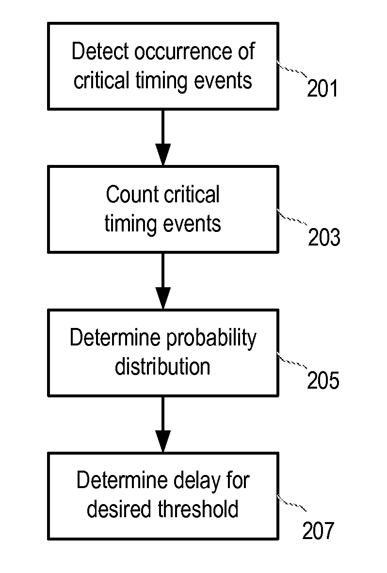
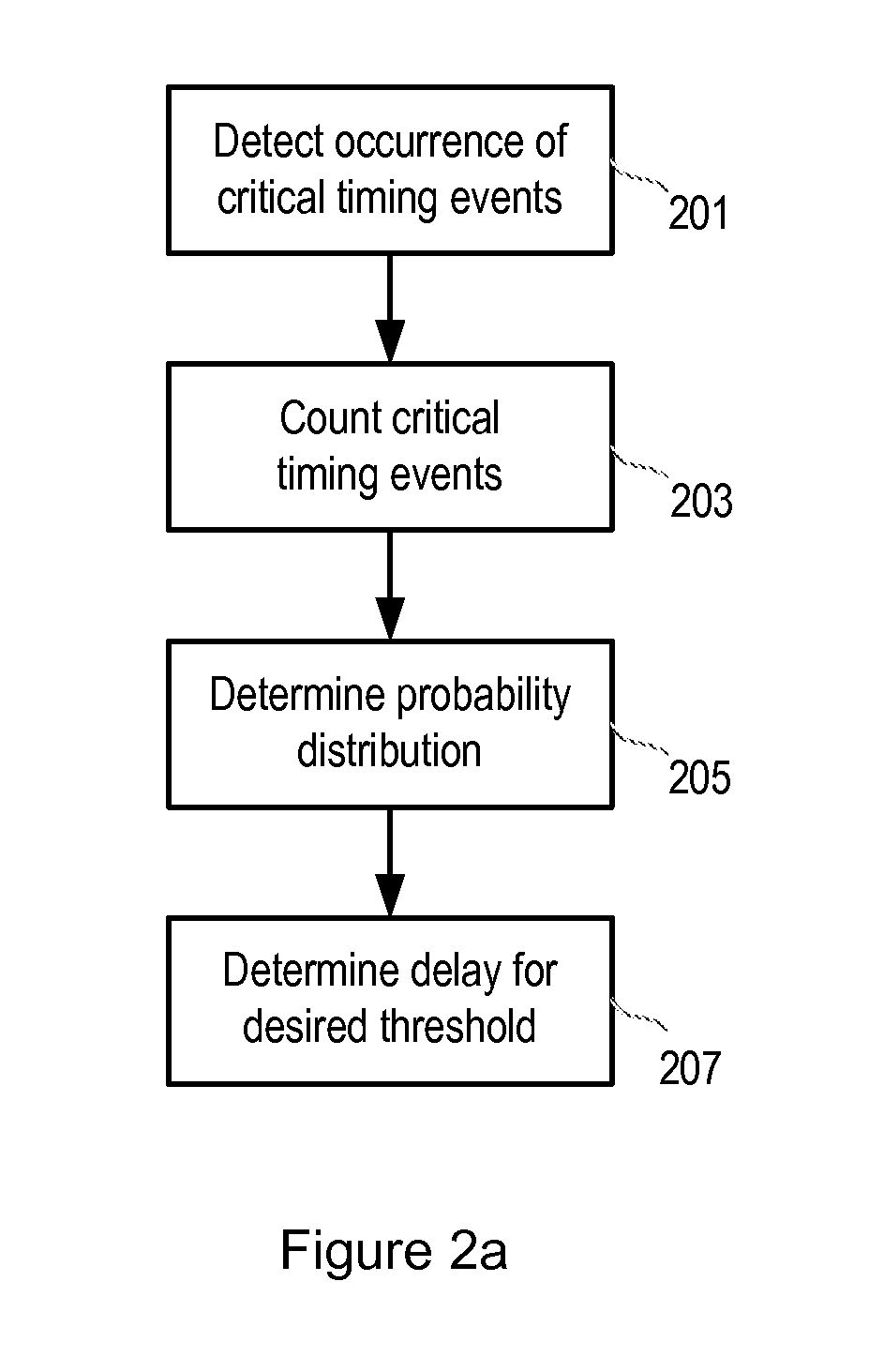
[0036]With reference to FIG. 2a, during the design phase of the functional circuit, each canary circuit 103_1 to 103_n detects critical timing events, step 201. The output of the canary circuits is connected to an analyser circuit 105 for receiving the critical timing event output from at least one of the plurality of canary circuits 103_1 to 103_n via simulation or static time analysis, described in more detail below, and for detecting, step 201, and maintaining a count, step 203, of the number of critical timing events that occur at each of a plurality of delay...


PUM


Abstract

An apparatus for monitoring timing of a plurality of critical paths of a functional circuit includes a plurality of canary circuits, each configured to be coupled to a critical path of a functional circuit for detecting and outputting critical timing events. Each canary circuit includes an adjustable delay element and an analyser circuit for receiving a count of the critical timing event output from at least one of the plurality of canary circuits for a predetermined time interval for a plurality of delay values of the adjustable delay elements and for determining a probability distribution of critical timing events of the at least one of the plurality of critical paths for the predetermined time interval for the plurality of delay values.

Description

CROSS-REFERENCE TO RELATED APPLICATION[0001]This application claims priority to European Patent Application No. 12167647.2 filed on May 11, 2012, the contents of which are hereby incorporated by referenceFIELD OF THE DISCLOSURE[0002]The present disclosure relates to an apparatus for monitoring timing of a plurality of critical paths to detect any critical timing events and adjust dynamically voltage and / or frequency to avoid violations.BACKGROUND TO THE DISCLOSURE[0003]Enabling systems to run at multiple frequency and voltage levels is a challenging process and requires characterization of the processor to ensure its correct operation at the required operating points. This means ensuring correct process operation with respect to a number of environmental and process related variabilities, such as unexpected voltage drops in the power supply network, temperature fluctuations, gate-length and doping concentration variations, etc. A minimum possible supply voltage for given maximum ope...

Claims


Application Information

Patent Timeline
Patent Type & Authority Applications(United States)
IPC IPC(8): G06F17/50G06F1/32
CPCG06F17/5031G06F1/3296G06F1/324G06F30/327G06F2119/12G06F30/398G06F30/3312G06F30/3315
Inventor GEMMEKE, TOBIASKONIJNENBURG, MARIO
Owner STICHTING IMEC NEDERLAND
Why Eureka
Try Eureka