Return-type current-reuse mixer

a frequency mixer and current-reuse technology, applied in the field of return-type current-reuse frequency mixers, can solve the problems of poor isolation effect between radio frequency signals and output intermediate frequency signals, poor frequency selectivity, noise, etc., and achieves simplified circuit structures, reduced power consumption, and high conversion gain

Inactive Publication Date: 2013-11-14
SOUTHEAST UNIV
View PDF1 Cites 8 Cited by
  • Summary
  • Abstract
  • Description
  • Claims
  • Application Information

AI Technical Summary

Benefits of technology

[0024]The frequency mixer comprises a transconductance / amplifier stage, a mixer stage, and high-pass and low-pass filter networks; the transconductance / amplifier stage employs a current reuse CMOS structure, wherein an input radio frequency signal is converted into radio frequency current; the current is filtered through the high-pass filter network to filter off the low frequency component and then fed into the mixer stage; in the mixer stage, intermediate frequency signal is generated and output under the modulation action of the mixer stage. The intermediate frequency signal is filtered through a low-pass filter network to filter off the high frequency component and then is sent again for input into the transconductance / amplifier stage, amplified by the transconductance / amplifier stage, and then output; the transconductance stage of the frequency mixer employs current reuse technology, and the input radio frequency signal and output intermediate frequency signal share the same transconductance / amplifier stage. Therefore, the frequency mixer of the present invention has advantages of reduced power consumption, simplified circuit structure, and high conversion gain.

Problems solved by technology

However, regenerative circuit in its early stage also faced some problems, for example, the circuit will amplify the noise infinitely when there is no signal input, causing hissing noise from the speaker; the emitted oscillating signal will interfere with other receivers; some circuit knowledge is required to accomplish adjustment of regenerative circuit, and the frequency selectivity is poor, etc.
Therefore, the effect of isolation between radio frequency signal and output intermediate frequency signal was poor, and the receiving quality was poor due to mutual interference.

Method used


Image

  • Return-type current-reuse mixer
  • Return-type current-reuse mixer
  • Return-type current-reuse mixer

Examples


Embodiment Construction

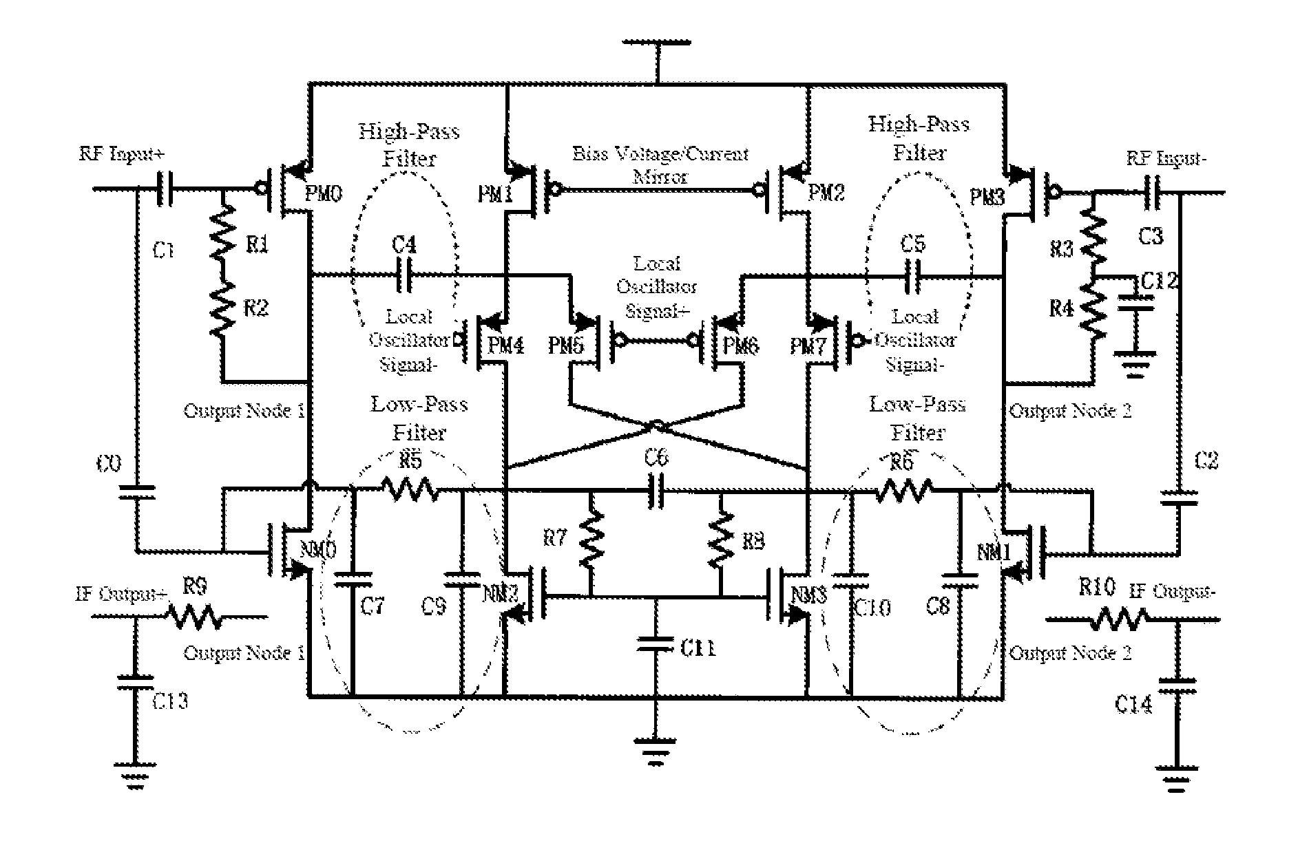
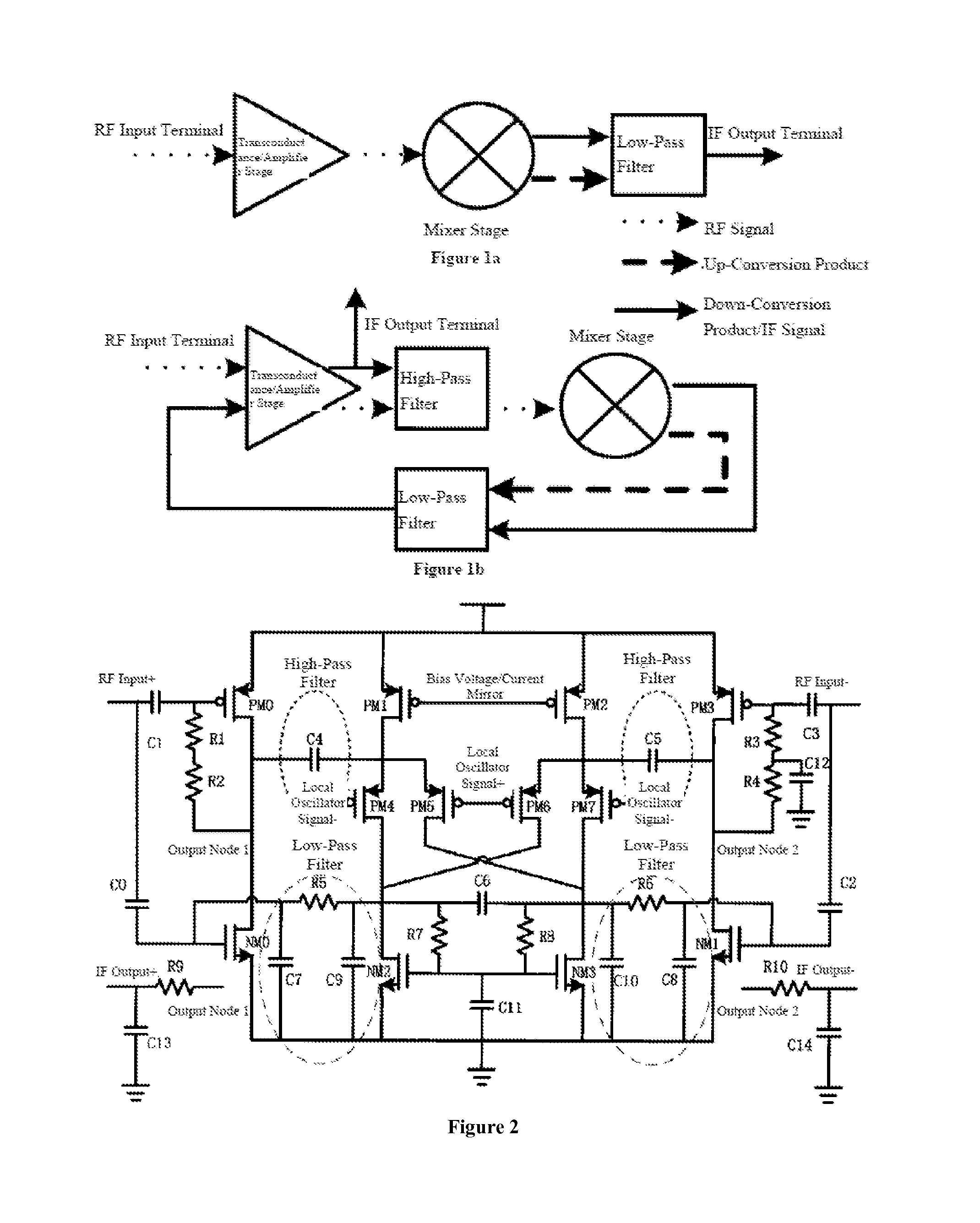
[0031]The main structure of the return-type current reuse frequency mixer of the present invention mainly comprises a transconductance / amplifier stage, a mixer stage, biasing circuits, and filter networks, etc. The transconductance / amplifier stage comprises P-channel metal oxide field effect transistors (hereinafter called as PMOS transistors) PM0 and PM3, and N-channel metal oxide field effect transistors (hereinafter called as NMOS transistors) NM0 and NM1. PM0, NM0, and PM3 and NM1 constitute a current reuse transconductance stage. NM0 and NM1 serve as amplifier transistors for the output intermediate frequency signal, and the final output signals are output from the drain electrodes of NM0 and NM1. Double balanced switches PM4-PM7 serve as the core circuit of frequency mixer, and the current bias is provided by bias transistors PM1 and PM2. The DC bias voltage for the transconductance stage is provided by the gate voltage of mixing load transistors NM2 and NM3. Capacitors C4 and...


PUM


Abstract

A return-type current-reuse mixer having a transconductance / amplification stage, a mixing stage, and a high-pass and a low-pass filter network. The transconductance / amplification stage has a current-reuse CMOS topology wherein an input frequency signal is converted into a frequency current, low-frequency components are removed from the frequency current by the high-pass filter network, the frequency current is fed into the mixing stage, modulation occurs in the mixing stage, and then an intermediate-frequency signal is generated and output. Once high-frequency components are removed from the intermediate-frequency signal by the low-pass filter network, the intermediate-frequency signal is sent again for input into the transconductance / amplification stage, then amplified in the transconductance / amplification stage and output. The mixer transconductance / amplification stage employs a current-reuse technique. The input frequency and the output intermediate-frequency signal share a common transconductance / amplification stage. The mixer reduces power consumption, simplifies the circuit topology, and provides high conversion gain.

Description

FIELD OF THE INVENTION [0001]The present invention relates to a return-type current reuse frequency mixer, which contains a transconductance / amplifier stage and a mixer stage. Radio frequency signal is down converted into intermediate frequency signal via transconductance stage and mixer stage, and then is fed back to the transconductance stage for intermediate frequency amplification; the amplified signal is output after being filtered by a first-order low-pass filter. The transconductance stage of the frequency mixer amplifies both the input radio frequency signal and output intermediate frequency signal; to ensure circuit stability, the radio frequency signal / intermediate frequency signal are coupled and isolated by means of low-pass / high-pass filter networks. The structure has advantages of reduced power consumption, simplified circuit structure and high conversion gain, and is applicable to low-power and low-cost constant-envelope communication standard.BACKGROUND OF THE INVENT...

Claims


Application Information

Patent Timeline
Patent Type & Authority Applications(United States)
IPC IPC(8): H03D7/14
CPCH03D7/1425
Inventor WU, JIANHUICHEN, CHAOLI, HONGSHI, LONGXINGWANG, ZIXUANSUN, JIEYE, ZHIYIZHANG, MENG
Owner SOUTHEAST UNIV
Why Eureka
Try Eureka