Electronic component
a technology of electronic components and components, applied in the direction of electrical apparatus construction details, electrical apparatus casings/cabinets/drawers, coupling device connections, etc., can solve the problems of mobile terminal breakdown and circuit board cracking, and achieve the effect of reducing the stress produced near the four corners of the circuit board, preventing cracking, and fractur
- Summary
- Abstract
- Description
- Claims
- Application Information
AI Technical Summary
Benefits of technology
Problems solved by technology
Method used
Image
Examples
first preferred embodiment
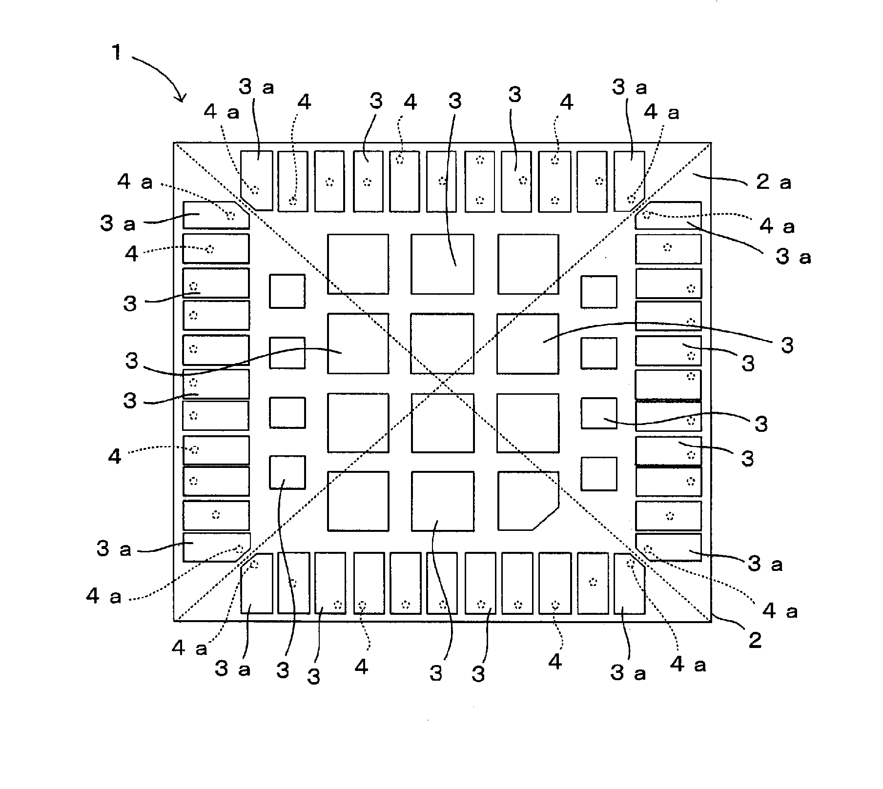
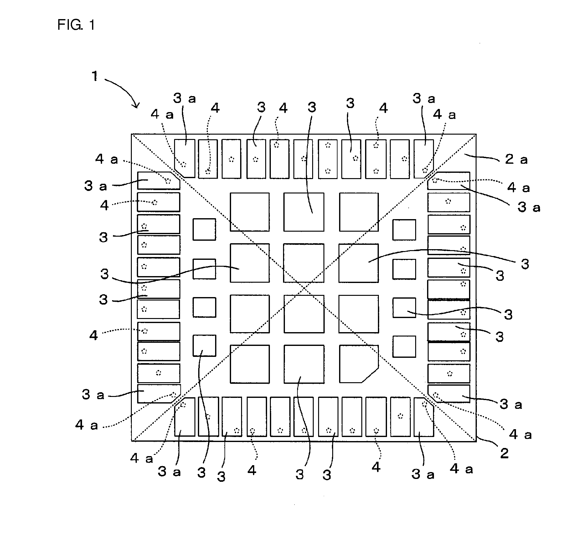
[0022]An electronic component according to a first preferred embodiment of the present invention will be described with reference to FIG. 1. FIG. 1 is a bottom view of the electronic component according to the first preferred embodiment of the present invention.
[0023]An electronic component 1 illustrated in FIG. 1 includes a circuit board 2 that preferably is a multilayered ceramic board, in which components, for example, a semiconductor element such as an amplifier, a diode, and a switch including a transistor or an FET, a resistor element, a capacitor element, and an inductor element, are mounted on at least a front surface (one principal surface), and land-shaped surface mounting electrodes 3 and 3a are mounted on a back surface 2a (the other principal surface). The electronic component 1 preferably is a module such as a Bluetooth (registered trademark) module, a wireless LAN module, or an antenna switch module for a cellular phone, for example. The unillustrated front surface of...
second preferred embodiment
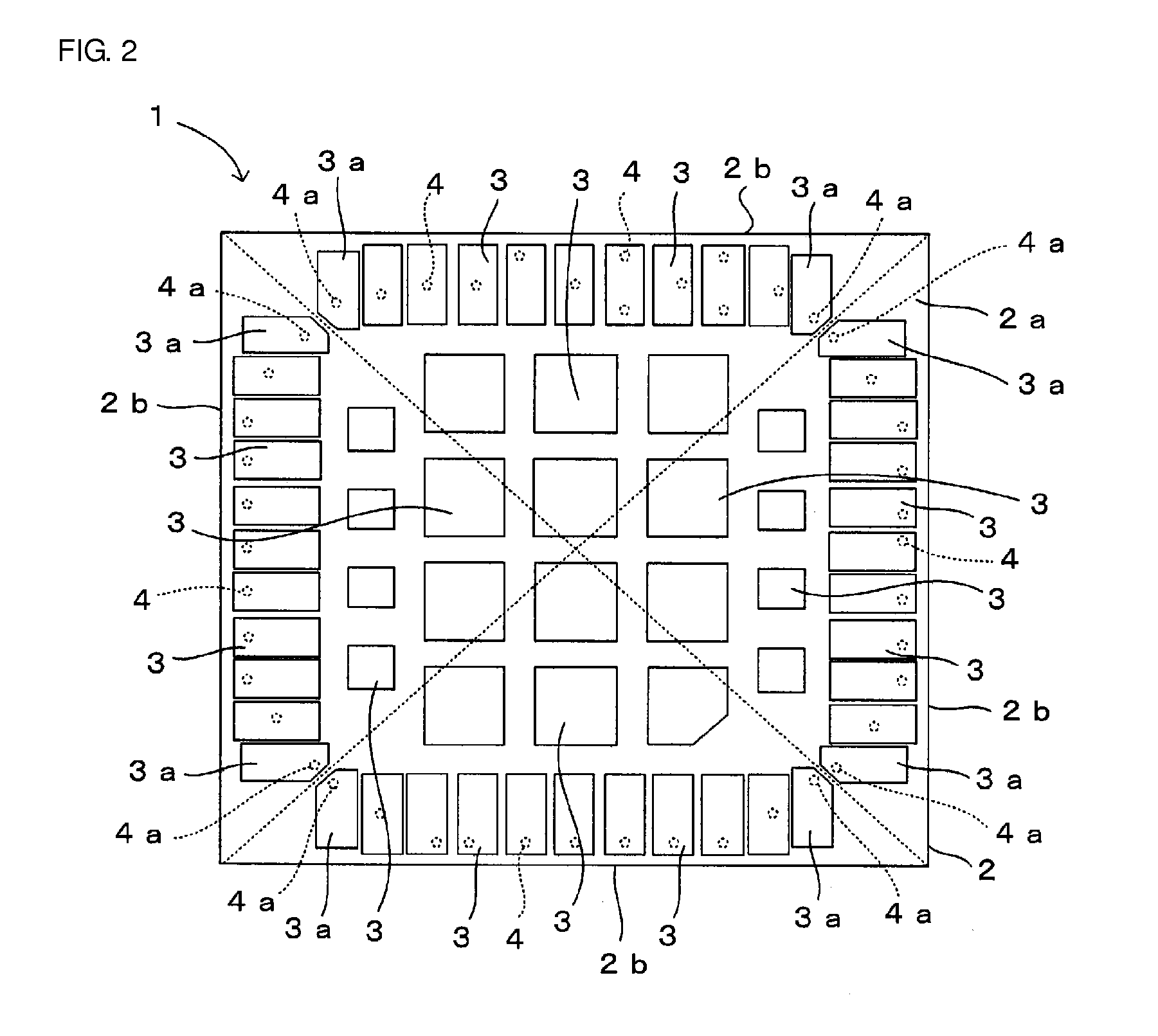
[0035]An electronic component according to a second preferred embodiment of the present invention will be described with reference to FIG. 2. FIG. 2 is a bottom view of the electronic component according to the second preferred embodiment of the present invention.
[0036]This preferred embodiment is different from the above-described first preferred embodiment in that, as illustrated in FIG. 2, mounting electrodes 3a near the corners are provided at positions farther from an outer edge 2b of a back surface 2a of a circuit board 2 than other mounting electrodes 3 arranged along the outer edge 2b, that is, at positions closer to the center of the back surface 2a. Since other structures are similar to those adopted in the above-described first preferred embodiment, they are denoted by the same reference numerals, and descriptions thereof are skipped.
[0037]According to this preferred embodiment, since the mounting electrodes 3a near the corners of the circuit board 2 are provided at the p...
third preferred embodiment
[0038]An electronic component according to a third preferred embodiment of the present invention will be described with reference to FIG. 3. FIG. 3 is a bottom view of the electronic component according to the third preferred embodiment of the present invention.
[0039]This preferred embodiment is different from the above-described first preferred embodiment in that, as illustrated in FIG. 3, a mounting electrode 3a near at least one corner is longer than other mounting electrodes 3 in a direction of one side of the circuit board 2 adjacent to the mounting electrode 3a near the corner. Since other structures are similar to those adopted in the above-described first preferred embodiment, they are denoted by the same reference numerals, and descriptions thereof are skipped.
[0040]According to this preferred embodiment, the mounting electrode 3a near at least one corner is longer than the other mounting electrodes 3 in the direction of one side of the circuit board 2 adjacent to the mount...
PUM
 Abstract
Description
Claims
Application Information
 - R&D
- Intellectual Property
- Life Sciences
- Materials
- Tech Scout
- Unparalleled Data Quality
- Higher Quality Content
- 60% Fewer Hallucinations
Browse by: Latest US Patents, China's latest patents, Technical Efficacy Thesaurus, Application Domain, Technology Topic, Popular Technical Reports.
© 2025 PatSnap. All rights reserved.Legal|Privacy policy|Modern Slavery Act Transparency Statement|Sitemap|About US| Contact US: help@patsnap.com


