

Non-liposomal systems for nucleic acid delivery
a nucleic acid and non-liposomal technology, applied in the direction of microcapsules, capsule delivery, biochemistry apparatus and processes, etc., can solve the problems of immune response, potential reversion, range of limitations, etc., and achieve the effect of enhancing silencing ability
- Summary
- Abstract
- Description
- Claims
- Application Information
AI Technical Summary
Benefits of technology
Problems solved by technology
Method used
Image

Examples
example 1
Characterization of SNALP Structure
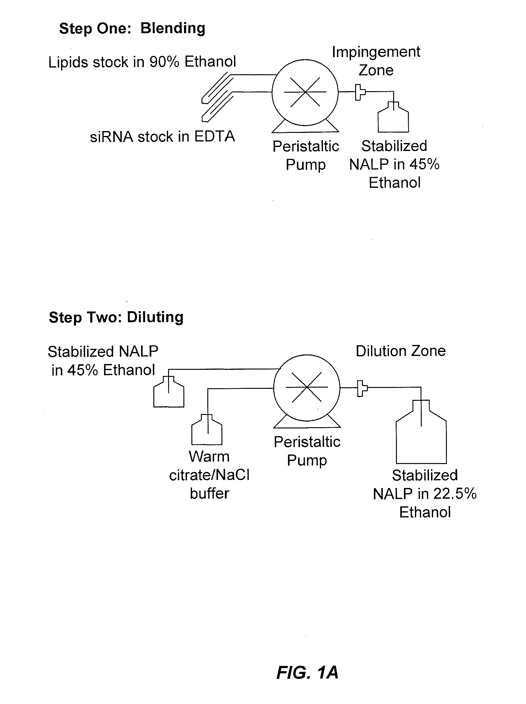
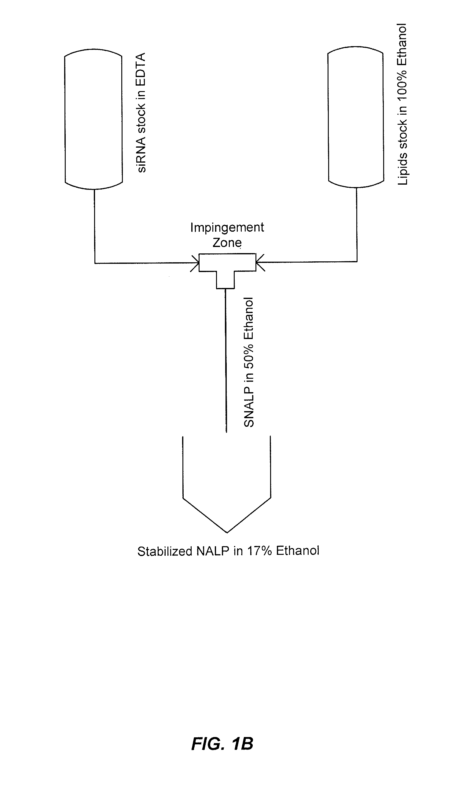
[0491]This example demonstrates that by controlling the lipid composition of the SNALP formulation as well as the particle formation process, novel non-lamellar lipid nanoparticles (e.g., SNALP) can be produced that have enhanced activity. In this example, SNALP formulations of varying compositions were prepared using either a Stepwise Dilution Method or a Direct Dilution Method to study the effects the manufacturing process and / or the lipid composition had on particle size, encapsulation efficiency and morphology.
[0492]The Stepwise Dilution Method (“SDM”), which is also referred to herein as the Lipomixer I process, as well as the apparatuses for carrying out the SDM are described in detail in U.S. Patent Publication No. 20040142025 and in Jeffs, et al., “A Scalable, Extrusion-Free Method for Efficient Liposomal Encapsulation of Plasmid DNA,” Pharmaceutical Research, 2005, Vol. 22, No. 3 pp 362-372, the disclosures of both of which are herein inco...
example 2
Further Characterization of SNALP Structure Using Cryo-TEM
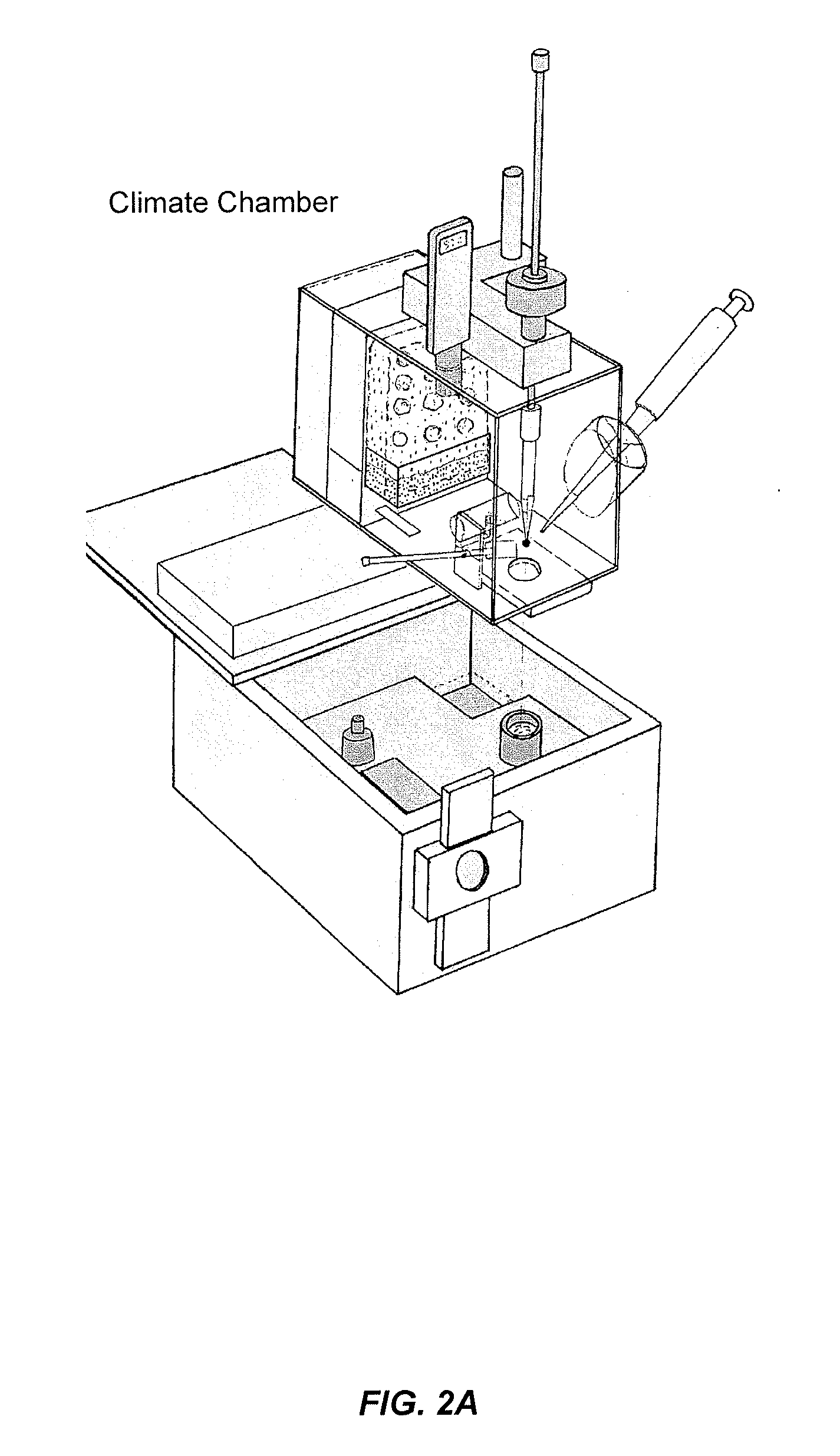
[0502]Various SNALP formulations prepared by the Stepwise Dilution Method and the Direct Dilution Method were further characterized by Cryo-Transmission Electron Microscopy (“Cryo-TEM”). As illustrated in FIGS. 2A-2C, Cryo-TEM is a microscopy technique, whereby a beam of electrons is transmitted through an ultra-thin frozen specimen, interacting with the speciment as it passes through. An image is then formed from the interaction of the electrons transmitted through the specimen, and the image is magnified and focused onto an imaging device.
[0503]Coded samples were sent to Uppsala University for Cryo-TEM imaging according to the method described by Almgren, M., et al., Colloid Surf. A 174, 3-21 (2000). Briefly, the samples were incubated at 25° C. for 20-30 minutes before preparation. The climate chamber conditions were: 25° C., with >98% relative humidity. 0.5 μL of sample solution was deposited on copper grid with perforate...
example 3
Characterization of 7:54 SNALP Formulation Using Cryo-TEM
[0520]In this example, the 7:54 formulation as well as variations of the 7:54 formulation were analyzed using methods similar to those set forth in Examples 1 and 2. All of the 7:54 SNALP formulations were prepared with an siRNA targeting polo-like kinase 1 (PLK-1) (Genbank Accession No. NM—005030) as the nucleic acid component. The PLK-1 siRNA sequence used in this study is provided in Table 8.
TABLE 8% 2′OMe-% ModifiedsiRNAPLK-1 siRNA SequenceModifiedin DS RegionPLK1424 2 / 65′-AGAUCACCCUCCUUAAAUAUU-3′ (SEQ ID NO: 1)9 / 42 = 21.4%7 / 38 = 18.4%3′-CUUCUAGUGGGAGGAAUUUAU-5′ (SEQ ID NO: 2)Column 1: The number after “PLK” refers to the nucleotide position of the 5′ base of the sense strand relative to the start codon (ATG) of the human PLK-1 mRNA sequence NM_005030. Column 2: 2′OMe nucleotides are indicated in bold and underlined. The 3′-overhangs on one or both strands of the siRNA molecule may alternatively comprise 1-4 deoxythymidine...
PUM
| Property | Measurement | Unit |
|---|---|---|
| Temperature | aaaaa | aaaaa |
| Fraction | aaaaa | aaaaa |
| Mass | aaaaa | aaaaa |
Abstract
Description
Claims
Application Information