Seal rings in electrochemical processors

a technology of electrochemical processors and sealing rings, which is applied in the direction of sealing devices, mechanical devices, and the details of semiconductor/solid-state devices, etc., can solve the problems of non-uniform plating, dry contact rings have their own disadvantages, and add to the time requirements and complexity of manufacturing processes. achieve the effect of improving yield, improving performance, and precise sealing dimensions

Inactive Publication Date: 2013-11-21
APPLIED MATERIALS INC
View PDF9 Cites 14 Cited by
  • Summary
  • Abstract
  • Description
  • Claims
  • Application Information

AI Technical Summary

Benefits of technology

[0005]A new seal ring for an electrochemical processor has now been invented. In one design, the new seal ring does not slip when sealed against a wafer surface. The seal ring may be on a rotor of the processor, with the seal ring having an outer wall joined to a tip arc. The outer wall may be a straight wall. A relatively rigid support ring may be attached to the seal ring, to provide a m

Problems solved by technology

This affect, referred to as “plate-up” changes the electric field around the contacts, causing non-uniform plating.
The metal plated onto the electrical contacts consequently must be removed, adding to the time requirements and complexity of the manufacturing process.
Although th

Method used


Image

  • Seal rings in electrochemical processors
  • Seal rings in electrochemical processors
  • Seal rings in electrochemical processors

Examples


Embodiment Construction

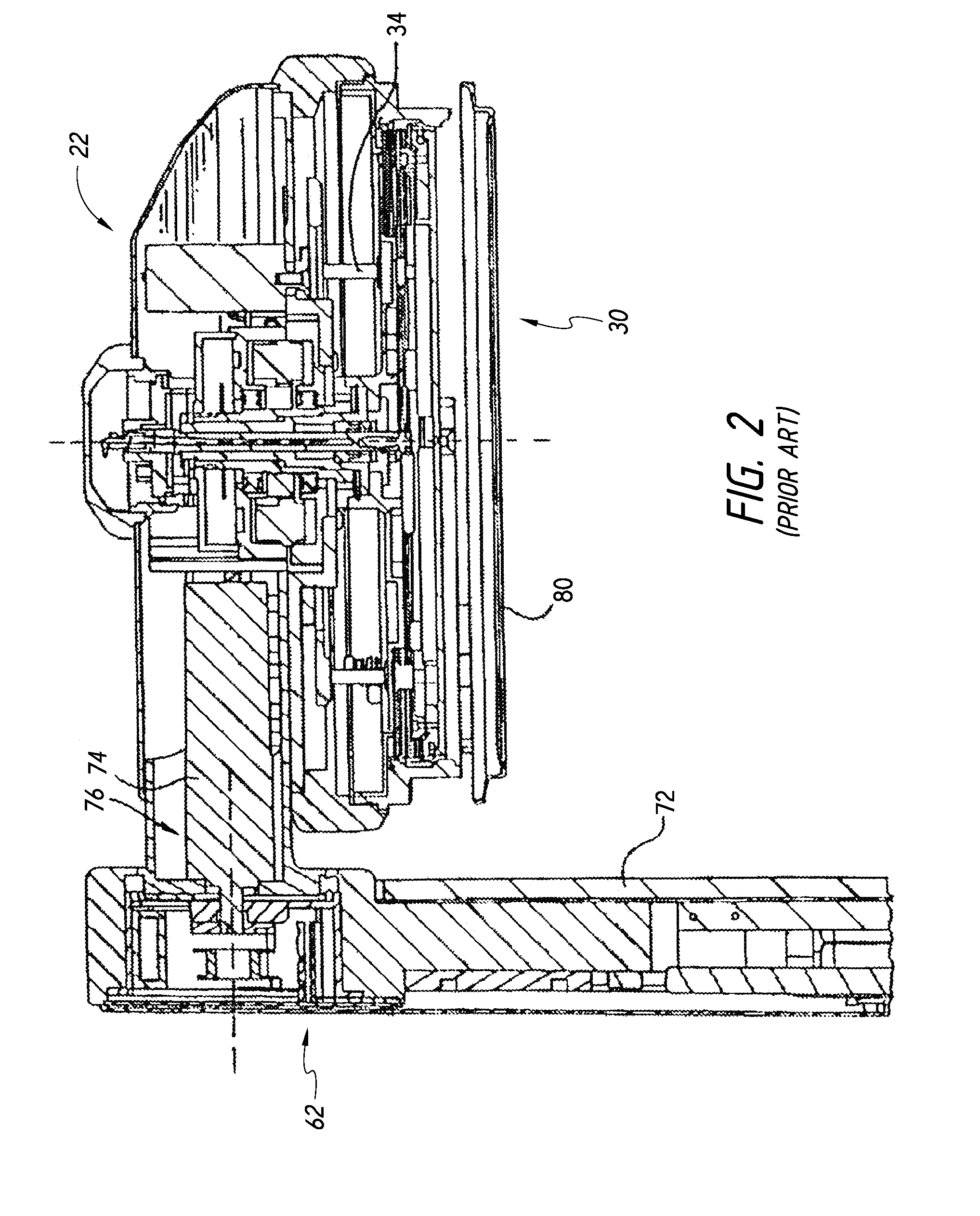
[0015]As shown in FIG. 1, an electrochemical processor 20 has a rotor 24 in a head 22. The rotor 24 includes a backing plate 26 and a contact ring 30 having a seal 80. Contact ring actuators 34 move the contact ring 30 vertically (in the direction T in FIG. 1), to engage the contact ring 30 and the seal 80 onto the down facing surface of a wafer or substrate 50. A bellows 32 may be used to seal internal components of the head. The contact ring typically has metal fingers that contact a conductive layer on the wafer 50. The head 22 is positioned to place the substrate 50 into a bath of liquid electrolyte held in a vessel 38 in a base 36. One or more electrodes are in contact with the liquid electrolyte. FIG. 1 shows a design having a center electrode 40 surrounded by a single outer electrode 42, although multiple concentric outer electrodes may be used. An electric field shaping unit 44 made of a di-electric material may be positioned in the vessel between the electrodes and the wafe...


PUM

PropertyMeasurementUnit
Angleaaaaaaaaaa
Angleaaaaaaaaaa
Diameteraaaaaaaaaa

Abstract

A seal ring for an electrochemical processor does not slip or deflect laterally when pressed against a wafer surface. The seal ring may be on a rotor of the processor, with the seal ring having an outer wall joined to a tip arc through an end. The outer wall may be a straight wall. A relatively rigid support ring may be attached to the seal ring, to provide a more precise sealing dimension. Knife edge seal rings that slip or deflect laterally on the wafer surface may also be used. In these designs, the slipping is substantially uniform and consistent, resulting in improved performance.

Description

BACKGROUND OF THE INVENTION[0001]Production of semiconductor integrated circuits and other micro-scale devices typically requires formation of multiple metal layers on a wafer or other substrate. By electroplating metals layers in combination with other steps, such as planarizing, etching and photolithography, patterned metal layers forming the micro-scale devices are created.[0002]Electroplating is performed with the substrate, or one side of the substrate, in a bath of liquid electrolyte, and with electrical contacts touching a conductive layer on the substrate surface. Electrical current is passed through the electrolyte and the conductive layer. Metal ions in the electrolyte deposit or plate out onto the substrate, creating a metal layer on the substrate. The metal ions also tend to plate out onto the electrical contacts as well. This affect, referred to as “plate-up” changes the electric field around the contacts, causing non-uniform plating. The metal plated onto the electrica...

Claims


Application Information

Patent Timeline
IPC IPC(8): C25D17/00
CPCC25D17/004H01L23/16C25D17/001C25D17/002F16J15/025F16J15/3204F16J15/3236F16J15/00F16J15/16
Inventor ZIMMERMAN, NOLAN L.MATTINGER, GEORGEWILSON, GREGORY J.ENGLHARDT, ERIC A.RAMASAMY, BALAMURUGAN
Owner APPLIED MATERIALS INC
Why Eureka
Try Eureka