Assembly and method of attaching stub shaft to drum of axial compressor rotor shaft

a technology of axial compressor and rotor shaft, which is applied in the direction of machines/engines, liquid fuel engines, lighting and heating apparatus, etc., can solve the problems of reducing the effectiveness of interference fitting, bolts are subject to harmonic imbalance and resonance, and the high speed at which stub shafts are usually rotated further complicates these problems. , to achieve the effect of reducing maintenance expenses and reducing manufacturing costs

Inactive Publication Date: 2013-11-21
ELLIOTT CO
View PDF5 Cites 1 Cited by
  • Summary
  • Abstract
  • Description
  • Claims
  • Application Information

AI Technical Summary

Benefits of technology

[0011]In view of the foregoing, a need exists for an assembly and method for attaching the stub shaft to the shaft drum of the axial flow compressor, whereby the need for through-bolts for preventing relative motion of the stub shaft to the shaft drum is eliminated. An additional need exists for providing an assembly and method for attaching the stub shaft to the shaft drum of the axial flow compressor, whereby the assembly and method lower manufacturing costs and reduce maintenance expenses.

Problems solved by technology

The magnitude of radial expansion of the stub shaft is usually smaller than the magnitude of radial expansion of the hollow drum, which reduces the effectiveness of the interference fit.
Numerous disadvantages are associated with the use of these conventional devices to prevent relative movement between the stub shaft and the shaft drum.
In embodiments where through-bolts are used, the bolts are subject to harmonic imbalance and resonance as the axial flow compressor is brought up to operating speed because the bolts must be of substantial length to extend along the entire stub shaft length.
High speeds at which stub shafts are usually rotated further complicate these problems.
Additionally, the through-bolts are fastened under a very high pre-stretch condition, which tends to weaken the bolts as the axial flow compressor is operated in multiple cycles.

Method used


Image

  • Assembly and method of attaching stub shaft to drum of axial compressor rotor shaft
  • Assembly and method of attaching stub shaft to drum of axial compressor rotor shaft
  • Assembly and method of attaching stub shaft to drum of axial compressor rotor shaft

Examples


Embodiment Construction

[0026]For purposes of the description hereinafter, spatial orientation terms, if used, shall relate to the referenced embodiment as it is oriented in the accompanying drawing figures or otherwise described in the following detailed description. However, it is to be understood that the embodiments described hereinafter may assume many alternative variations and embodiments. It is also to be understood that the specific devices illustrated in the accompanying drawing figures and described herein are simply exemplary and should not be considered as limiting.

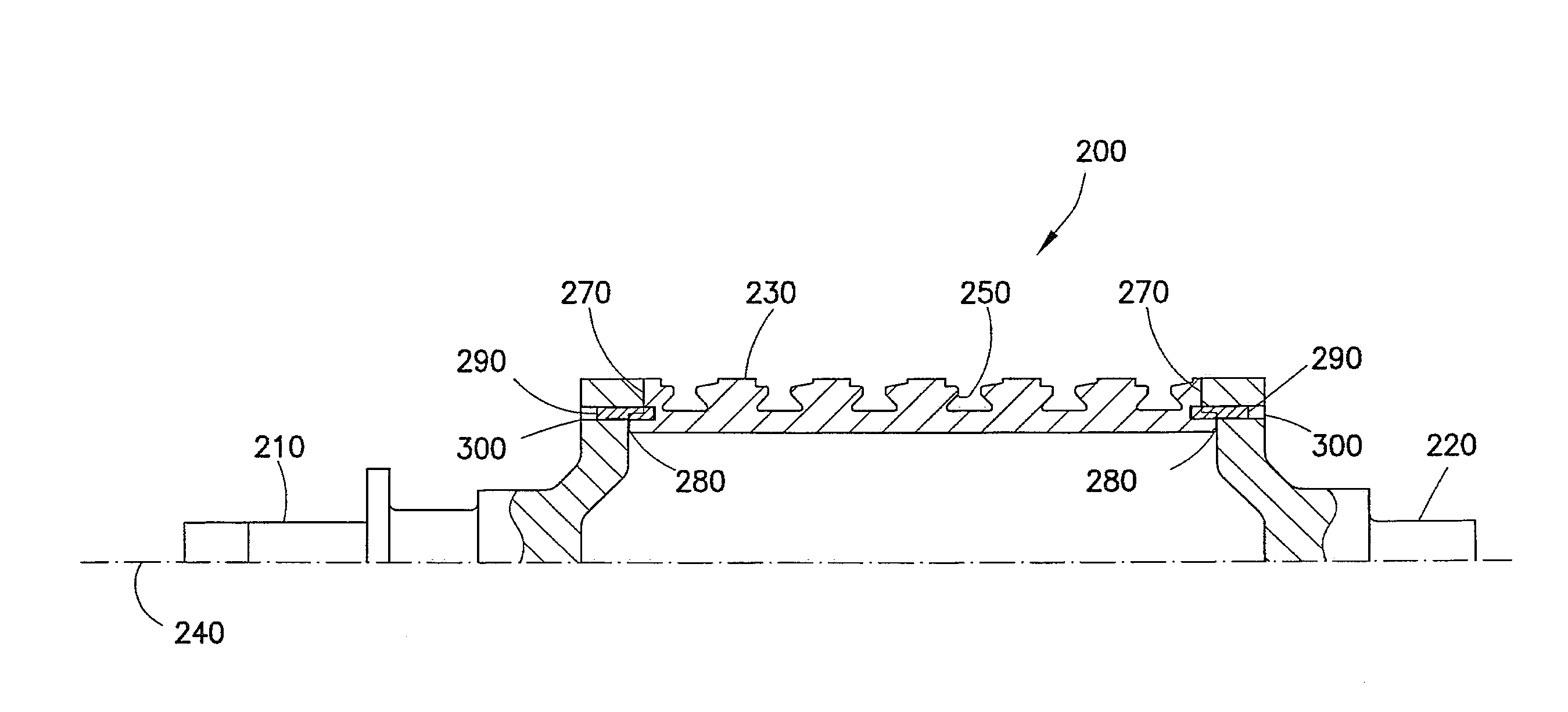
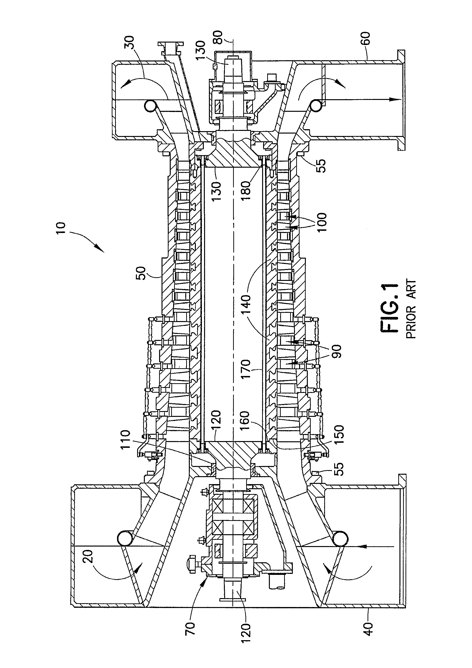
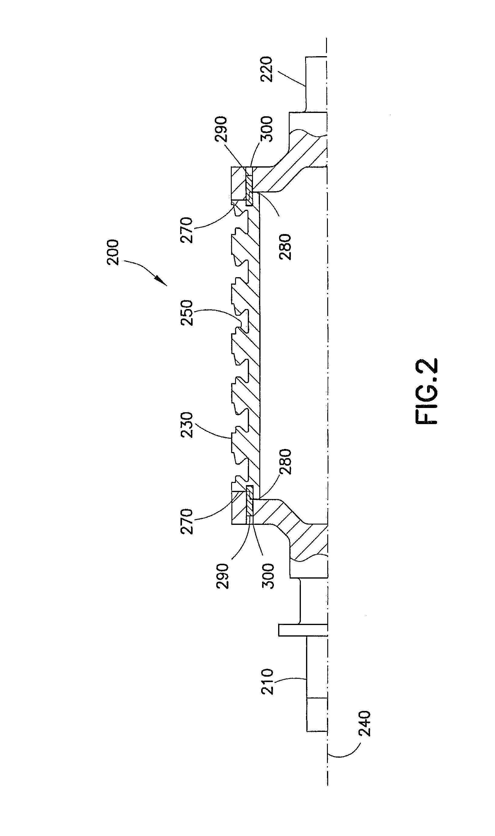
[0027]Referring to the drawings in which like reference characters refer to like parts throughout the several views thereof, the present invention is generally described in terms of an assembly and method of attaching the stub shaft to the drum of the axial compressor rotor shaft. With reference to FIG. 1, an axial compressor 10 in accordance with a prior art embodiment is shown. Axial compressor 10 includes an inlet end 20 provided...


PUM

PropertyMeasurementUnit
outer circumferenceaaaaaaaaaa
longitudinal lengthaaaaaaaaaa
circumferenceaaaaaaaaaa

Abstract

An assembly and method for an axial compressor includes an axial shaft extending between an inlet casing and a discharge casing along the longitudinal length of a compressor housing. The axial shaft assembly includes a first stub shaft, a second stub shaft, and a hollow shaft drum having a longitudinal axis. The first stub shaft and the second stub shaft are coupled to opposing ends of the shaft drum along its longitudinal axis. A plurality of keys is disposed in a radial arrangement near the outer circumference of the first and second stub shafts and the shaft drum. A plurality of pins engage the plurality of keys, whereby the pins prevent the shaft drum from rotating axially relative to the first stub shaft and the second stub shaft and prevent the shaft drum from axially and radially separating from the stub shafts.

Description

BACKGROUND OF THE INVENTION[0001]1. Field of the Invention[0002]This invention relates, in general, to axial compressors and, more particularly, to a method of attaching a stub shaft to a drum of an axial flow compressor rotor shaft.[0003]2. Description of the Related Art[0004]Turbo machines, such as centrifugal flow compressors, axial flow compressors, and turbines are utilized in various industries. Axial flow compressors, in particular, have a widespread use in power stations, jet engine applications, gas turbines, and automotive applications. Axial flow compressors are also commonly used in large scale industrial applications, such as air separation plants and hot gas expanders used in the oil refinery industry.[0005]Axial flow compressors generally include a rotating shaft coupled to a central drum having a number of airfoil blades circumferentially arranged and spaced apart in multiple rows along the axial length of the drum. The airfoil blades rotate between a corresponding n...

Claims


Application Information

Patent Timeline
Patent Type & Authority Applications(United States)
IPC IPC(8): F04D29/053
CPCF04D29/053F04D29/266F04D29/321Y10T29/49236F25B3/00
Inventor WATSON, ANDREW PAUL
Owner ELLIOTT CO
Why Eureka
Try Eureka