Coordination of cam timing and blow-through air delivery

a technology of cam timing and blow-through air, which is applied in the direction of electrical control, process and machine control, etc., can solve the problems of undesirable power lag, torque may not be available, power, fuel efficiency, emissions-control performance of a boosted engine may suffer, etc., to achieve greater fuel efficiency, lower emissions, and power. the effect of reducing emissions

Inactive Publication Date: 2013-11-21
FORD GLOBAL TECH LLC
View PDF10 Cites 22 Cited by
  • Summary
  • Abstract
  • Description
  • Claims
  • Application Information

AI Technical Summary

Benefits of technology

[0002]A boosted engine may offer greater fuel efficiency and lower emissions than a naturally aspirated engine of similar power. During transient conditions, however, the power, fuel efficiency, and emissions-control performance of a boosted engine may suffer. Such transient conditions may include rapidly increasing or decreasing engine load, engine speed, or mass air flow. For example, when the engine load increases rapidly, a turbocharger compressor may require increased torque to deliver an increased air flow. Such torque may not be available, however, if the turbine that drives the compressor is not fully spun up. As a result, an undesirable power lag may occur before the intake air flow builds to the required level.

Problems solved by technology

During transient conditions, however, the power, fuel efficiency, and emissions-control performance of a boosted engine may suffer.
Such torque may not be available, however, if the turbine that drives the compressor is not fully spun up.
As a result, an undesirable power lag may occur before the intake air flow builds to the required level.
However, the inventors herein have identified potential issues with such an approach.
As one example, the valve timing corresponding to the high valve overlap position may not be a timing that is optimal for engine performance.
Consequently, the high valve overlap position may degrade brake specific fuel consumption (BSFC) as well as the indicated engine torque production.
As such, this degrades engine fuel economy and performance.
If the required response time is faster than can be provided by the VCT device, engine performance and fuel economy may be further degraded.
As such, outside this range, engine torque output may be affected and / or combustion stability may be degraded.

Method used


Image

  • Coordination of cam timing and blow-through air delivery
  • Coordination of cam timing and blow-through air delivery
  • Coordination of cam timing and blow-through air delivery

Examples


Embodiment Construction

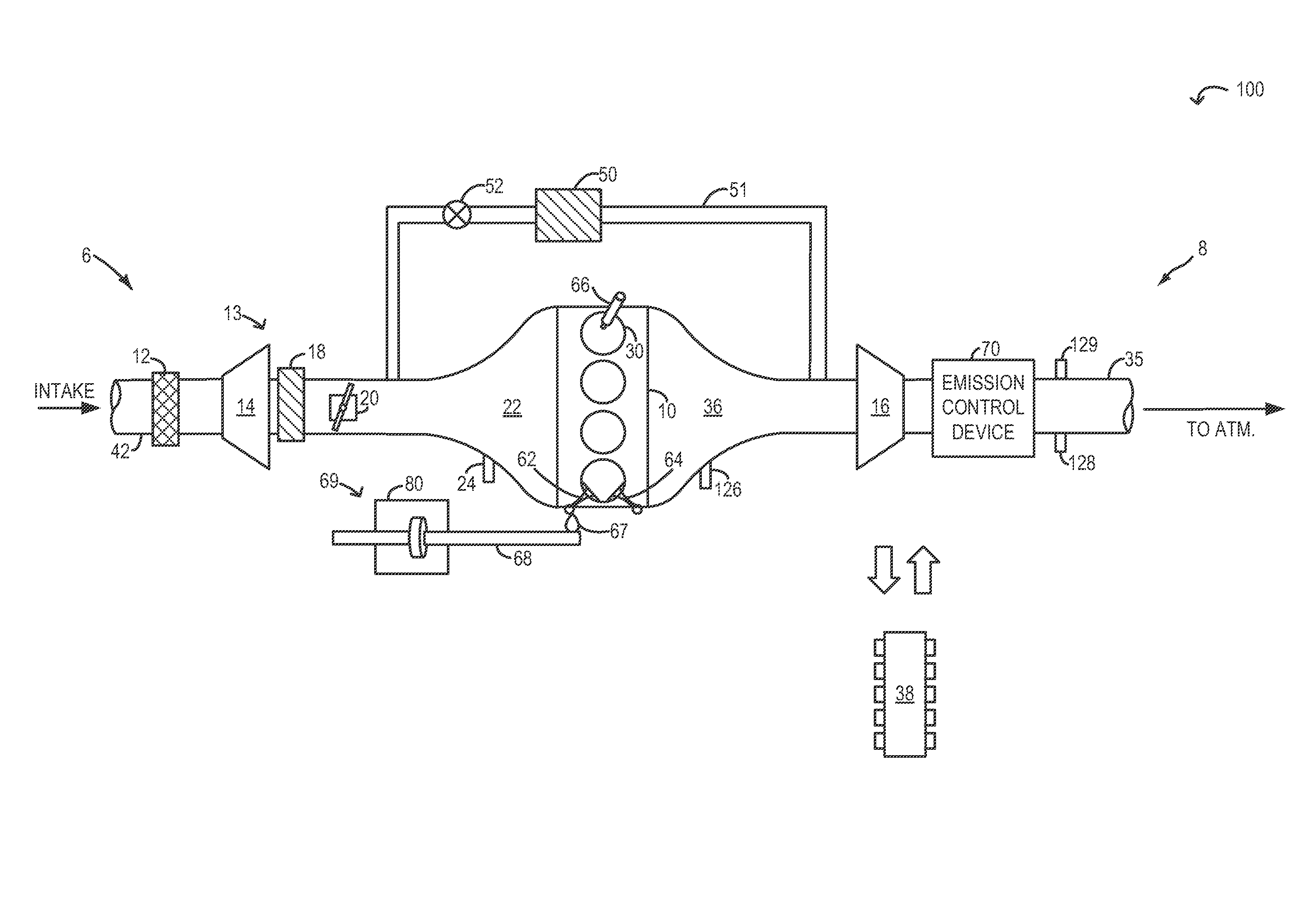
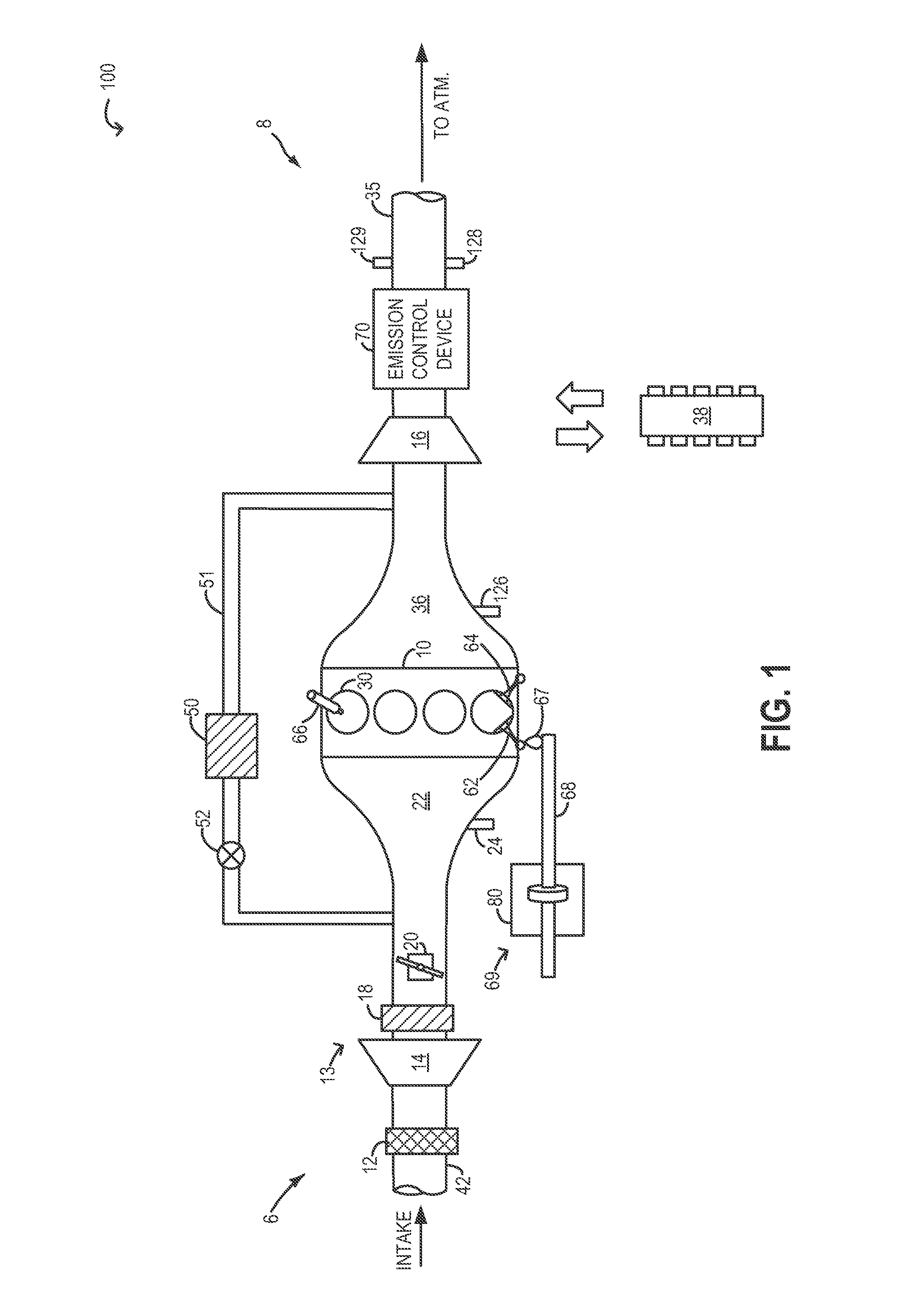
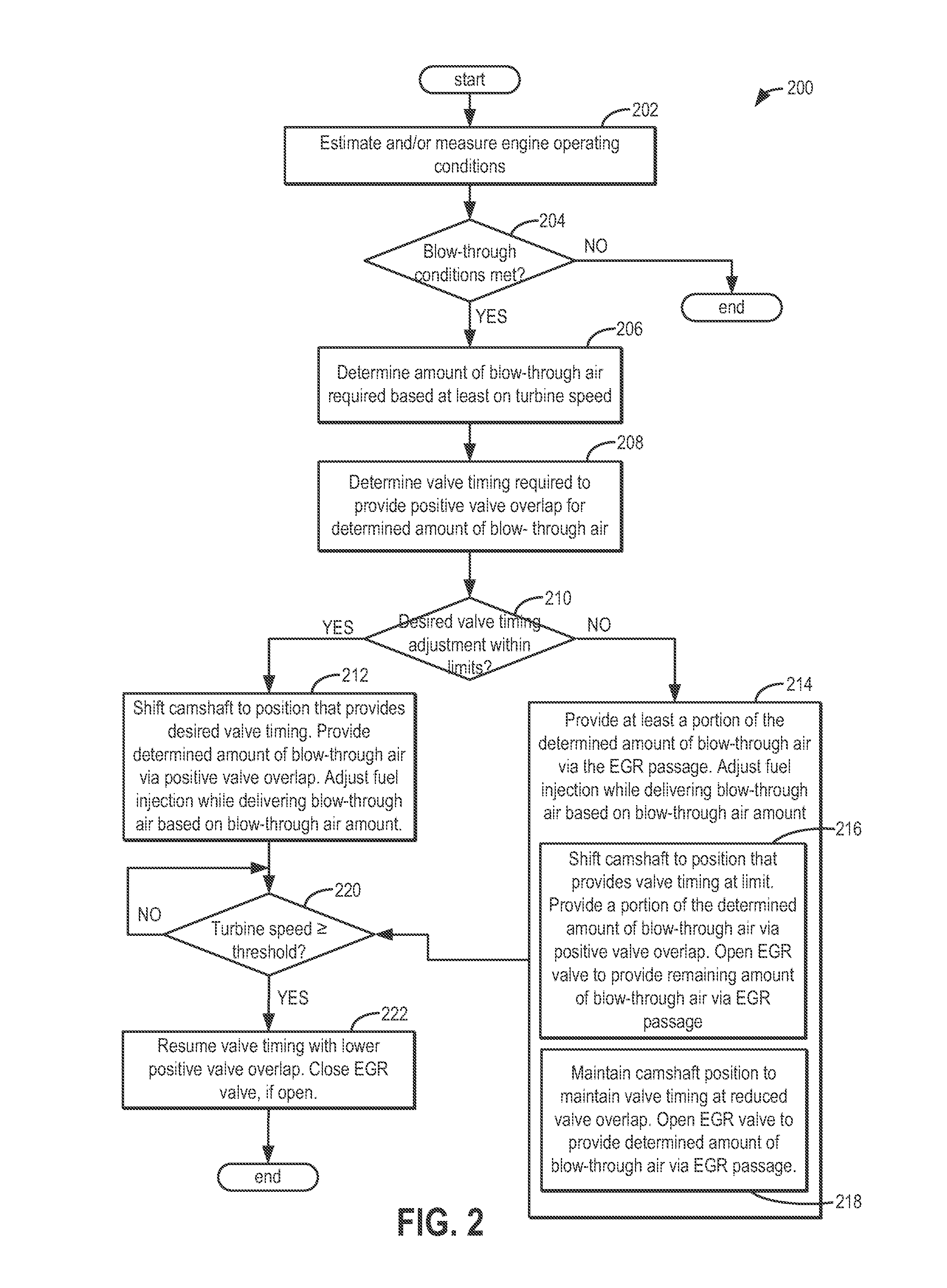
[0013]Methods and systems are provided for directing an amount of intake air from an intake manifold to an exhaust manifold of an engine system (such as the engine system of FIG. 1) via engine cylinders using positive valve overlap and / or via an EGR passage. In response to a tip-in, an engine controller may be configured to perform a control routine, such as the example routine of FIG. 2, to adjust a variable cam timing device to adjust intake and / or exhaust valve timings of an engine cylinder towards positive valve overlap so as to provide an amount of blow-through air via the cylinders. However, if the VCT adjustment degrades engine torque output and combustion stability, the controller may be configured to direct at least a portion of the blow-through air via an EGR passage of the engine system. The controller may also determine a ratio of blow-through air delivered via positive valve overlap relative to delivered via an EGR passage based on engine operating conditions. A fuel in...


PUM


Abstract

Methods and systems are provided for reducing turbo lag by directing intake air from an intake manifold to an exhaust manifold. The intake air may be directed via an EGR passage by opening an EGR valve or by may be directed via engine cylinders by increasing positive valve overlap. Amounts of air directed via external EGR and air directed via positive valve overlap are based on engine operating conditions.

Description

TECHNICAL FIELD[0001]This application relates to the field of motor-vehicle engineering, and more particularly, to air induction in motor vehicle engine systems.BACKGROUND AND SUMMARY[0002]A boosted engine may offer greater fuel efficiency and lower emissions than a naturally aspirated engine of similar power. During transient conditions, however, the power, fuel efficiency, and emissions-control performance of a boosted engine may suffer. Such transient conditions may include rapidly increasing or decreasing engine load, engine speed, or mass air flow. For example, when the engine load increases rapidly, a turbocharger compressor may require increased torque to deliver an increased air flow. Such torque may not be available, however, if the turbine that drives the compressor is not fully spun up. As a result, an undesirable power lag may occur before the intake air flow builds to the required level.[0003]It has been recognized previously that a turbocharged engine system may be ada...

Claims


Application Information

Patent Timeline
Patent Type & Authority Applications(United States)
IPC IPC(8): F02D9/02F02D41/30
CPCF02B37/12F02B37/168F02B37/20F02D13/0261F02D23/02F02D41/0007F02D41/005F02D41/0065F02D2041/001F02M26/05Y02T10/12Y02T10/40F02D13/0215F02D41/0077F02D41/38F02D2041/389
Inventor ROLLINGER, JOHN ERICRICHARDS, ADAM J.WADE, ROBERT ANDREWBELL, DAVID
Owner FORD GLOBAL TECH LLC
Why Eureka
Try Eureka