Multiple Panel Heat Exchanger
a heat exchanger and multi-panel technology, applied in indirect heat exchangers, lighting and heating apparatus, separation processes, etc., can solve the problems of high energy cost, low energy efficiency, unsafe drinking water produced as a byproduct of chilling air for other reasons than water production, etc., and achieve versatile and scalable effects
- Summary
- Abstract
- Description
- Claims
- Application Information
AI Technical Summary
Benefits of technology
Problems solved by technology
Method used
Image
Examples
embodiment 300
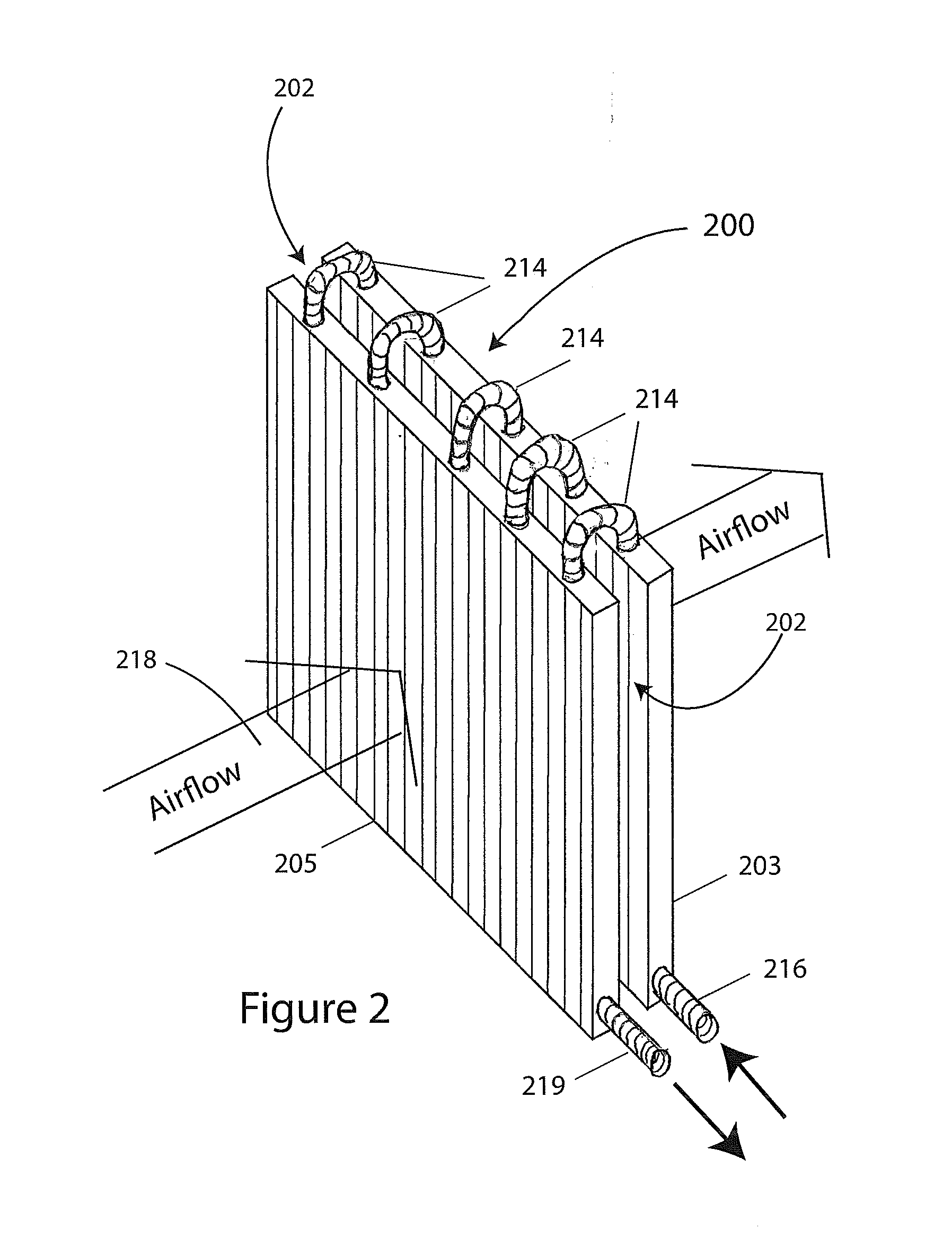
[0049]Turning now to FIG. 3, there is illustrated a diagrammatic perspective view of an alternative evaporator embodiment 300 of evaporator 200. In evaporator 300, the upstream panel 303 is connected to the downstream panel 305 by a valve 321 that is operable to restrict refrigerant flow between the panels. Despite panels 303 and 305 being connected by valve 321, evaporator 300 is still a considered to be a single unit because the valve must not be entirely closed for operation of the vapor-compression refrigeration system. As in evaporator 200, evaporator 300 is illustrated having only two interconnected panels for the purpose of simplicity. Refrigerant inlet 316, refrigerant outlet 319, and the valve connection 321 are placed so as to promote the greatest traverse by the gaseous refrigerant of the interiors of the panels to maximize the chilling potential.
[0050]Operation of valve 321 to restrict refrigerant flow rate between panels 305 and 303 can result in a temperature different...
embodiment 400
[0051]With reference now to FIG. 4, there is illustrated a diagrammatic perspective of an evaporator embodiment 400 that is similar to evaporator 300 that is shown in FIG. 3 with the exception of the upstream panel 405 and downstream panel 403 are of different size. Specifically, upstream panel 405 is smaller than downstream panel 403 which has the effect of reduced pre-cooling on airflow 402. In the representatively illustrated embodiment, upstream panel 405 has a vertical length that is about half of the vertical length of the downstream panel 403, and a horizontal length this about the same. Evaporator 400 is not limited to this arrangement, and relative dimensions between the upstream panel 405 and the downstream panel 403 may be configured as desired based upon required pre-cooling. Inlet 416, outlet 419, and valve 421 are similarly placed to those shown in FIG. 3. This embodiment can be used when little pre-cooling load is anticipated and in which the capital cost of the parts...
embodiment 500
[0052]With reference now to FIG. 5, there is illustrated a diagrammatic side elevation of an evaporator embodiment 500 that is similar to evaporator 300 that is shown in FIG. 3 with the exception of the upstream panel 505 and downstream panel 503 are of different thickness. Specifically, upstream panel 505 has a thickness x that is less than the thickness y of downstream panel 503. Reducing thickness of upstream panel 505 relative to the downstream panel 503 lowers the refrigeration or cooling capacity of the upstream panel 505 relative to the downstream panel 503, and thus provides a reduce pre-cooling of air 518.
[0053]The construction of evaporator 500 differs from that of evaporator 400 by causing air incident upon the upstream panel 503 to be first be entirely incident upon the downstream panel 505. Whereas in evaporator 400, a first portion of air incident upon the upstream panel 403 was first caused to be incident upon the downstream panel 405, and a second portion of air inci...
PUM
| Property | Measurement | Unit |
|---|---|---|
| Thickness | aaaaa | aaaaa |
| Flow rate | aaaaa | aaaaa |
| Area | aaaaa | aaaaa |
Abstract
Description
Claims
Application Information
 - R&D
- Intellectual Property
- Life Sciences
- Materials
- Tech Scout
- Unparalleled Data Quality
- Higher Quality Content
- 60% Fewer Hallucinations
Browse by: Latest US Patents, China's latest patents, Technical Efficacy Thesaurus, Application Domain, Technology Topic, Popular Technical Reports.
© 2025 PatSnap. All rights reserved.Legal|Privacy policy|Modern Slavery Act Transparency Statement|Sitemap|About US| Contact US: help@patsnap.com


