Spring type one-way clutch

a one-way clutch and spring technology, applied in the field of spring type one-way clutches, can solve the problems of increasing the size of the one-way clutch, small torque transmission capacity, etc., and achieve the effects of reducing local stress concentration, minimizing damage, and improving the durability of the clutch spring

Inactive Publication Date: 2013-11-28
NTN CORP
View PDF1 Cites 7 Cited by
  • Summary
  • Abstract
  • Description
  • Claims
  • Application Information

AI Technical Summary

Benefits of technology

[0033]According to any of the first to third inventions, since the large-diameter coil spring portion is connected to the small-diameter coil spring portion, which is located in, and wound in a different direction from, the large-diameter coil spring portion, through the transition portion extending radially inwardly from the winding end point of the large-diameter coil spring portion in a spiraling pattern in the direction in which the large-diameter coil spring portion is wound, it is possible to reduce local stress concentration on the transition portion while rotation is being transmitted from the driving member to the driven member. This minimizes damage to the transition portion due to fatigue, thus improving durability of the clutch spring.

Problems solved by technology

One drawback of this type of clutches is their small torque transmission capacity.
If it is desired to transmit larger torque, it is necessary to use a clutch spring with a large number of turns, which increases the size of the one-way clutch.

Method used


Image

  • Spring type one-way clutch
  • Spring type one-way clutch
  • Spring type one-way clutch

Examples


first embodiment

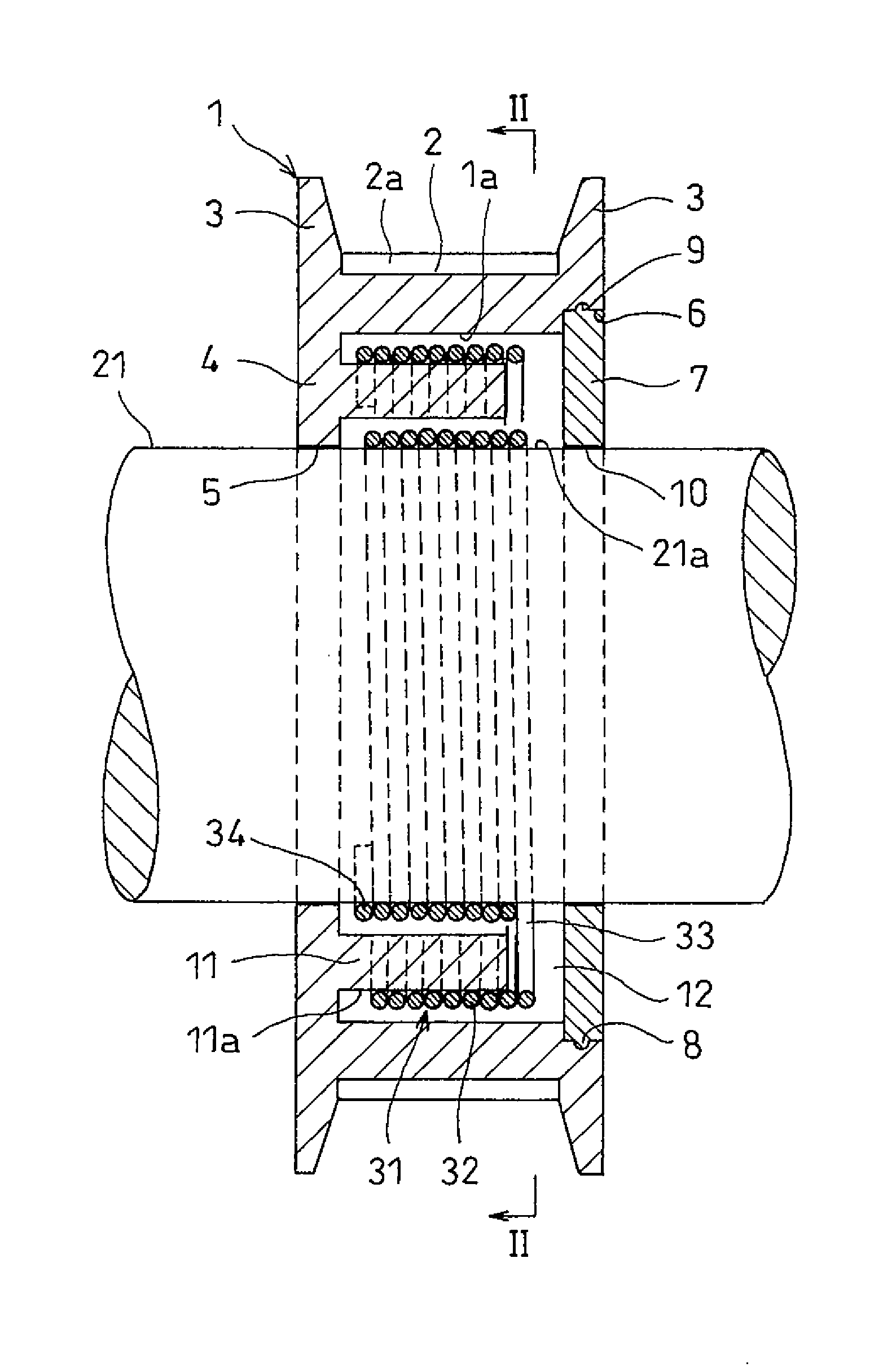
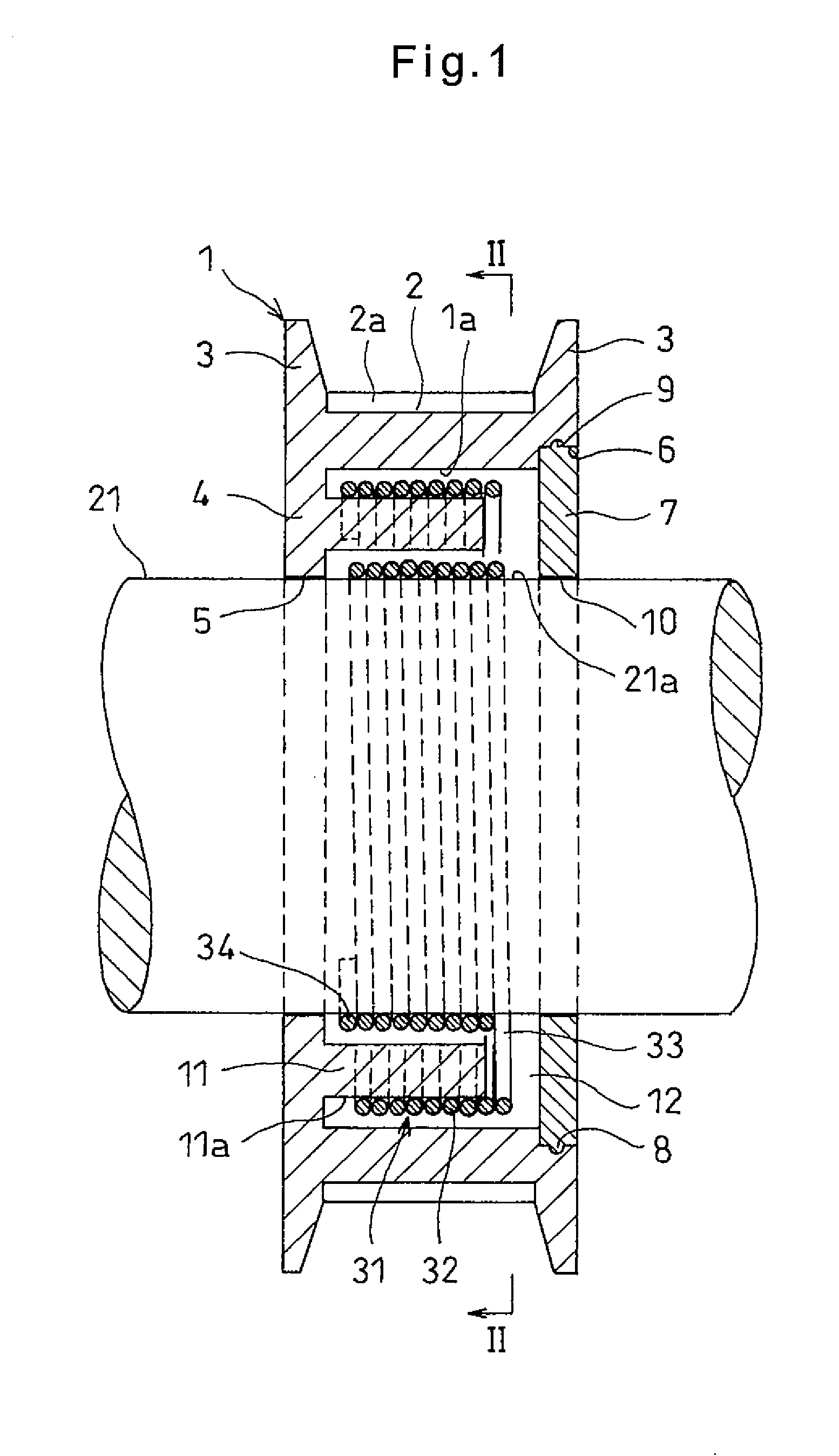
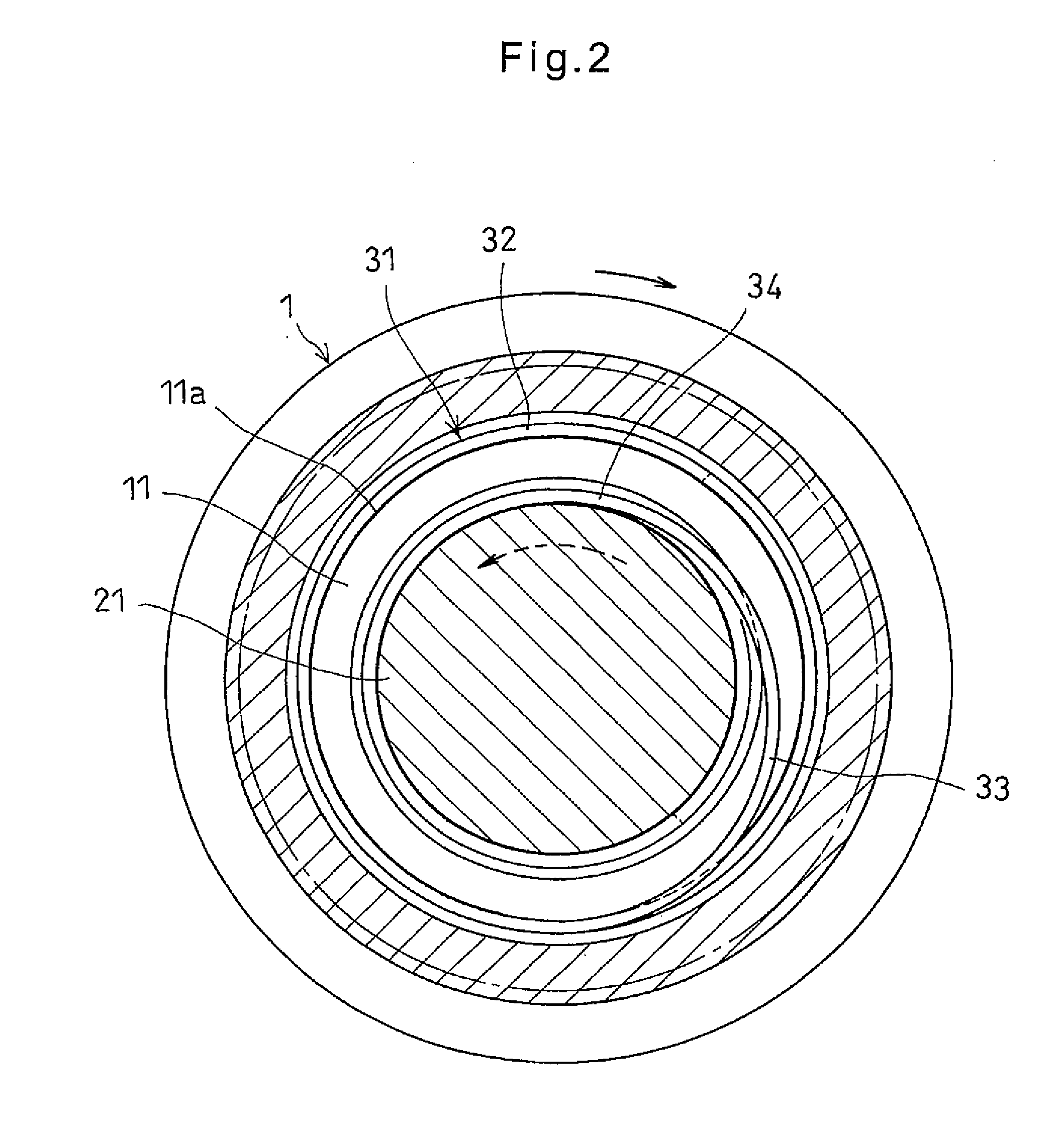
[0049]Now referring to the drawings, the embodiments of the present invention are described. FIGS. 1 to 3 show the spring type one-way clutch of the As shown in FIGS. 1 and 2, this one-way clutch includes an outer ring 1 as an outer member, and a rotary shaft 21 as an inner member which is inserted in the central portion of the outer ring 1 such that the outer ring 1 and the rotary shaft 21 are rotatable relative to each other.

[0050]The outer ring 1 shown is a toothed pulley having a radially outer belt guide surface 2 formed with circumferentially equidistantly spaced apart, axially extending teeth 2a, and flanges 3 provided at the respective axial ends of the belt guide surface 2. But the outer ring 1. according to the present invention is not limited to a pulley but may be e.g. a gear.

[0051]The outer ring 1 includes, at one axial end thereof, an inwardly extending flange 4 having a radially inner radial bearing surface 5. The outer ring 1 is formed with a large-diameter recess 6...

second embodiment

[0067]As in the second embodiment, by forming the spiral groove 13 in the distal end surface of the inner tubular portion 11 in which the transition portion 33 of the clutch spring 31 is received, stress applied to the transition portion 33 while torque is being transmitted between the outer ring 1 and the rotary shaft 21 is received by the inner wall of the spiral groove 13. This effectively prevents damage to the transition portion 33.

[0068]FIGS. 6 and 7 show the spring type one-way clutch according to the third embodiment of the present invention. This embodiment differs from the spring type one-way clutch of the second embodiment in that a radially outwardly extending hook 35 is provided at the winding start point of the large-diameter coil spring portion 32 which is engaged in an axially extending engaging groove 14 formed in the cylindrical radially inner surface 1a of the outer ring 1. Otherwise, this embodiment is structurally identical to the second embodiment. Thus, like e...

third embodiment

[0069]As shown in the third embodiment, by providing the hook 35 at the winding start point of the large-diameter coil spring portion 32 which is engaged in the axially extending engaging groove 14 formed in the outer ring 1, it is possible to reliably transmit the rotation of the outer ring 1 to the large-diameter coil spring portion 32 if the outer ring 1 is used as the driving member. While the rotation of the outer ring 1 is not supposed to be transmitted to the rotary shaft 21, slip reliably occurs between, and only between, the contact portions of the small-diameter coil spring portion 34 and the cylindrical radially outer surface 21a of the rotary shaft 21.

[0070]FIG. 8 shows the spring type one-way clutch according to the fourth embodiment of the present invention. In this embodiment, the lid 7 has an annular protrusion 15 formed on its inner side surface and fitted in the distal end portion of the inner tubular portion 11. Otherwise, this embodiment is structurally identical...


PUM


Abstract

A spring type one-way clutch includes an outer ring rotatable about a rotary shaft and having an inner tubular portion, and a clutch spring mounted in the outer ring. The clutch spring includes a large-diameter coil spring portion, a transition portion connected to the winding end of the large-diameter coil spring portion, and a small-diameter coil spring portion connected to the radially inner end of the transition portion and wound in the opposite direction from the large-diameter coil spring portion. When the outer ring is rotated in the direction opposite the winding direction of the large-diameter coil spring portion, the large and small-diameter coil spring portions are radially compressed and pressed against the inner tubular portion and the rotary shaft, allowing the rotary shaft to rotate together with the outer ring. The transition portion spirals radially inwardly in the winding direction of the large-diameter coil spring portion.

Description

TECHNICAL FIELD[0001]This invention relates to a spring type one-way clutch configured to transmit the rotation of a driving member in one direction to a driven member.BACKGROUND ART[0002]One-way clutches used e.g. in paper feeders of printers, copiers, facsimile machines, etc. include spring type clutches, which include a clutch spring adapted to be selectively pressed against and released from a driving or driven member, thereby selectively transmitting torque.[0003]Spring type one-way clutches include those having a clutch spring in the form of a single-layered spring, as disclosed in the below identified Non-patent document 1 and Patent document 1, and those having a double-layered clutch spring, as disclosed in Patent document 2.[0004]A single-layered spring type one-way clutch includes a driving shaft (driving arbor), a driven shaft (driven arbor) coaxial with the driving shaft, and a spring fitted over the end portions of both shafts such that when the driving shaft is rotate...

Claims


Application Information

Patent Timeline
Patent Type & Authority Applications(United States)
IPC IPC(8): F16D41/20F16D41/12
CPCF16D41/203F16D41/12E05Y2201/49E05Y2800/205E05Y2800/22F16D41/20F16D41/206F16D48/00
Inventor TAKADA, SEIICHISATOU, CHIYORI
Owner NTN CORP
Why Eureka
Try Eureka