Method and Device for Treating Opaque Fluids with UV Radiation

a technology of opaque fluid and radiation treatment, applied in the field of liquid treatment, can solve the problems of clogging equipment and piping handling cutting fluid, difficult to reach all parts of the volume of liquid to be treated, and breaking down the function of cutting fluid, etc., to achieve the effect of powerful treatment mechanism and enhanced

Inactive Publication Date: 2013-11-28
WALLENIUS WATER AB
View PDF18 Cites 0 Cited by
  • Summary
  • Abstract
  • Description
  • Claims
  • Application Information

AI Technical Summary

Benefits of technology

[0025]There are a number of benefits with the present invention. By placing a treatment unit inside a volume of fluid to be treated, no fluid transport or conveyor mechanisms are necessary for the treatment process. By creating radicals, a very powerful treatment mechanism is obtained, capable of handling the fluid in the volume.
[0026]An advantage is that the treatment unit is capable of creating photo-ionization effects that are used in the treatment process. Additionally or ins

Problems solved by technology

The more the liquid becomes filled with particles and the like matter increasing the opacity of the liquid, the more difficult it becomes to reach all parts of the volume of liquid to be treated.
Cutting fluids often comprise an emulsion of oil and water, where the water makes them susceptible to bacteria and other micro-organisms, leading to odours, in turn breaking down of the function of the cutting fluid and clogging of equipment and piping handling the cutting fluid.
Further the cutting fluids become increasingly loaded with foreign matter from the machining during use.
A major problem in this context is the opacity of the cutting fluid, which is worsened during use by foreign matter such as cutting chips, as well as micro-organism, bacteria and/or fungi growing in the fluid.
A major drawback with the device of U.S. Pat. No. 6,344,176 is the limited treatment capacity due to that only thin films can be treated, i.e. very small volumes of cutting fluid, during a time period.
Even though the increased energy inpu

Method used


Image

  • Method and Device for Treating Opaque Fluids with UV Radiation
  • Method and Device for Treating Opaque Fluids with UV Radiation
  • Method and Device for Treating Opaque Fluids with UV Radiation

Examples


Embodiment Construction

[0032]The present invention relates to a method of treating fluids, and in particular fluids that are opaque.

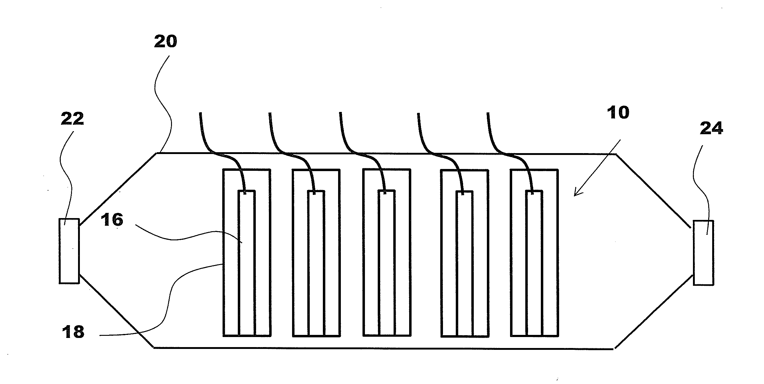
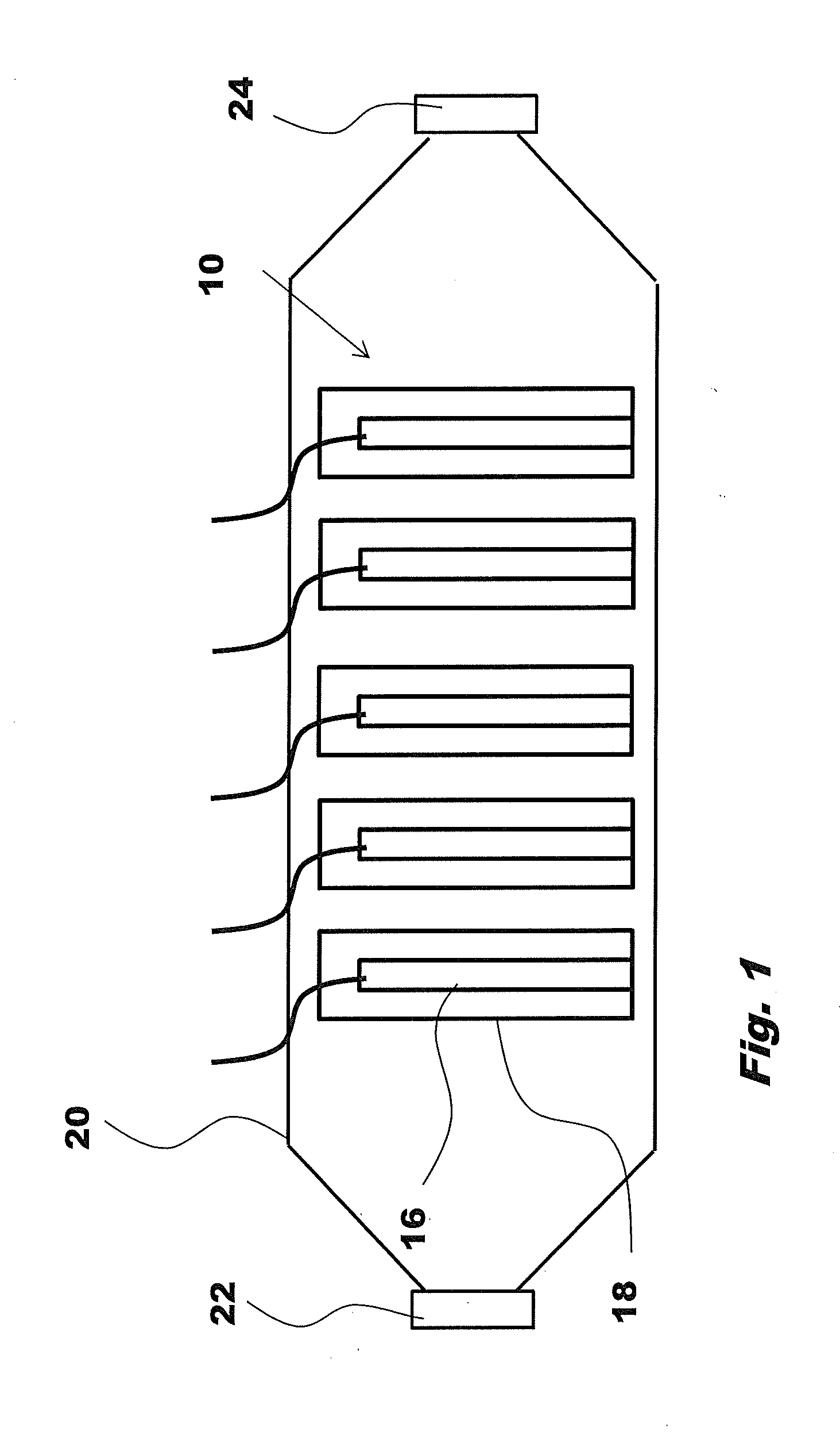
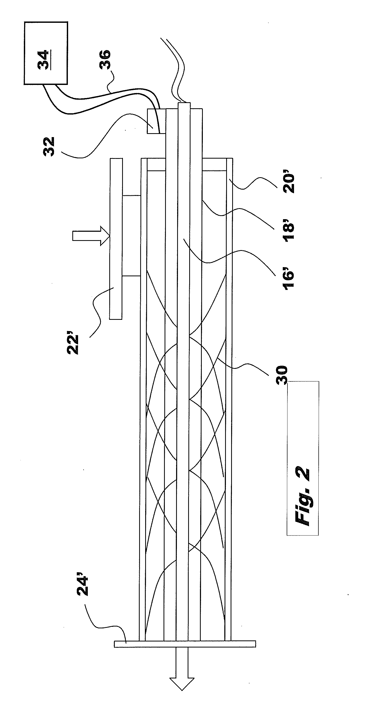
[0033]According to the invention shown in the drawing, a treatment unit 10 is arranged. The treatment unit 10 comprises at least one radiation source 16 capable of creating radiation energy in the liquid. The radiation source is preferably capable of creating radiation in the UV region, due to the positive effects that UV radiation possess. In order to create a good treatment environment and in order to maximize the treatment efficiency of the UV radiation, different measures are provided. One such measure for the treatment unit 10 is to position a transparent glass cover 18 or wall between the UV radiation source 16 and the fluid 14 to be treated. In order to create a desired photo-ionisation effect, which is very effective in treating the liquid, the glass cover 18 is made of very pure quartz glass. Preferred wavelengths are in the region of 100 nm to 220 nm, with preferabl...


PUM

PropertyMeasurementUnit
Flow rateaaaaaaaaaa
Volumeaaaaaaaaaa
Permeabilityaaaaaaaaaa

Abstract

The present invention relates to a method for treating opaque fluids, comprising the steps of placing a treatment unit inside a volume of fluid to be treated, which treatment unit comprises a UV radiation member capable of emitting UV radiation, 5 radiating said volume of fluid with UV radiation, whereby said UV radiation is capable of creating radicals in said fluid, which radicals react with matter in the fluid, thereby treating it.

Description

TECHNICAL FIELD[0001]The present invention relates to a method for treating liquids and in particular liquids that are opaque. The present invention in particular relates to a method utilizing radiation technologies.BACKGROUND OF THE INVENTION[0002]There are a number of devices on the market that are capable of treating, and in particular purifying, liquids. In many instances, members capable of generating UV radiation are used in the treatment process, and in particular UV radiation of certain wave-lengths that can create different reaction components such as ozone, hydrogen peroxide, radicals, to mention a few. In order to increase the performance of the cleaning process, some treatment devices are arranged with catalysts that are capable of creating e.g. photo-catalytic reactions for producing the treatment components.[0003]The above mentioned treatment methods have a good performance when treating liquids that possess a good transmissibility, i.e. the radiation from the UV gener...

Claims


Application Information

Patent Timeline
IPC IPC(8): B01J19/12
CPCB01J19/123A23C3/076C10M175/04C02F1/325C02F2201/3225C02F2201/3227C02F2201/324C02F2201/328C02F2303/04C02F2305/10C10M175/0066C02F1/32
Inventor ALANDER, EVA
Owner WALLENIUS WATER AB
Why Eureka
Try Eureka