Packaging for a fiber optic component and manufacturing method thereof

a technology of fiber optic components and packaging, which is applied in the field of packaging can solve the problems of high optical radiation fluencies high optical power levels may also leak out of fiber optic components, and the heating of packages, so as to minimize the transfer of thermal expansion induced strain, reduce the temperature increase of the package, and reduce the effect of thermal expansion

Active Publication Date: 2013-11-28
ROFIN SINAR LASER
View PDF9 Cites 2 Cited by
  • Summary
  • Abstract
  • Description
  • Claims
  • Application Information

AI Technical Summary

Benefits of technology

[0015]Considerable benefits are gained with aid of the present invention. Because the second support member has a coefficient of thermal expansion substantially smaller than the first coefficient of thermal expansion, the material of the first support member can be so selected as to efficiently dissipate heat generated by free-space radiation that gets absorbed by the first support member. In other words, temperature increase of the package can be minimized since no strict restriction to the magnitude of the first coefficient of thermal expansion is

Problems solved by technology

When inside of a high-power fiber laser, the fiber optic components may be subject to high optical radiation fluencies.
However, under some conditions relatively high optical power levels may also leak out of the fiber optic component into free space inside the mechanical package of the component.
Such free-space radiation within the package of the component will eventually be absorbed by the package, which results in heating of the package.
As a result of that, failure of a component may occur if such temperature variations have not been considered in the design of the package of the component.
Therefore, if the fiber op

Method used


Image

  • Packaging for a fiber optic component and manufacturing method thereof
  • Packaging for a fiber optic component and manufacturing method thereof
  • Packaging for a fiber optic component and manufacturing method thereof

Examples


Embodiment Construction

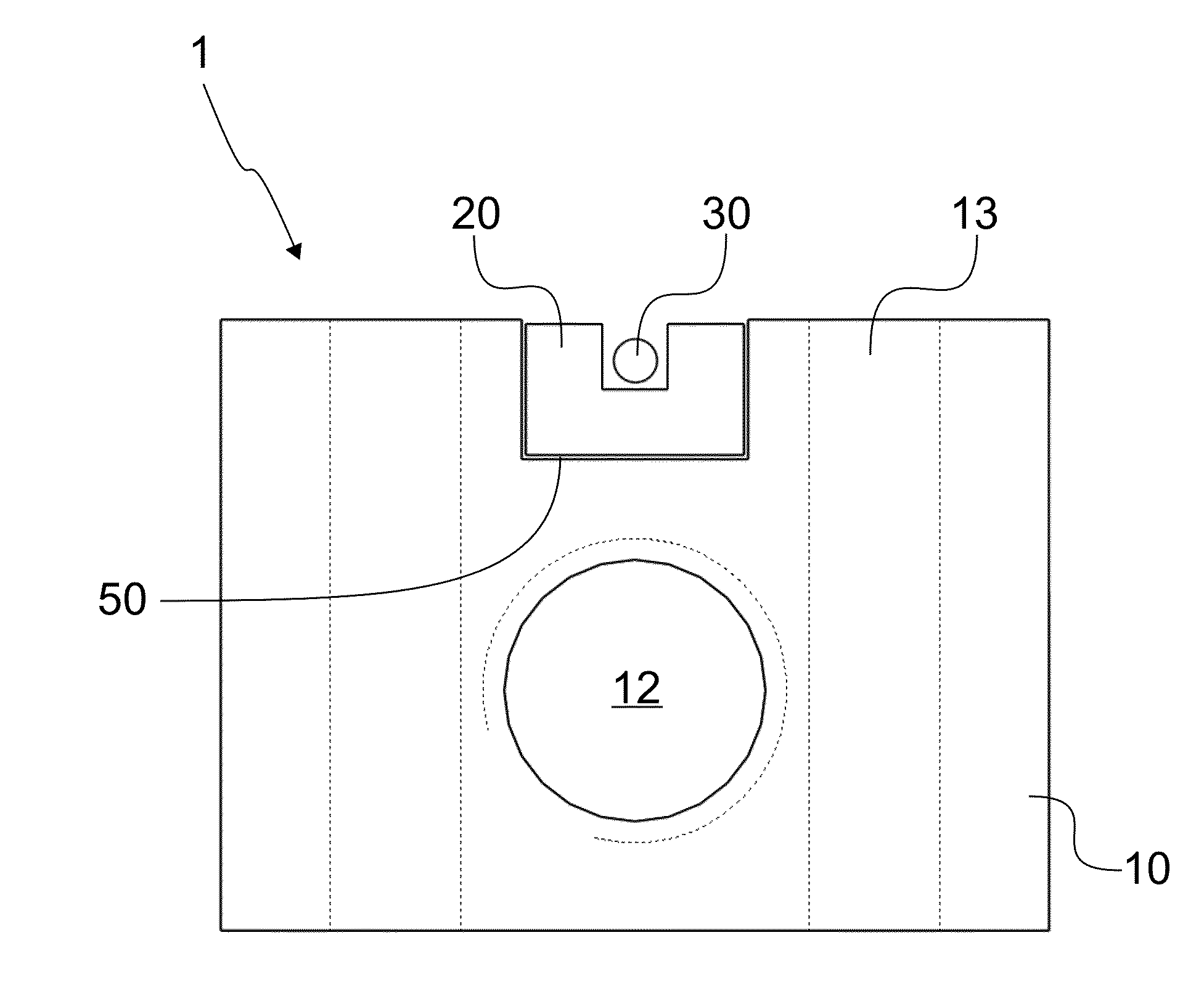
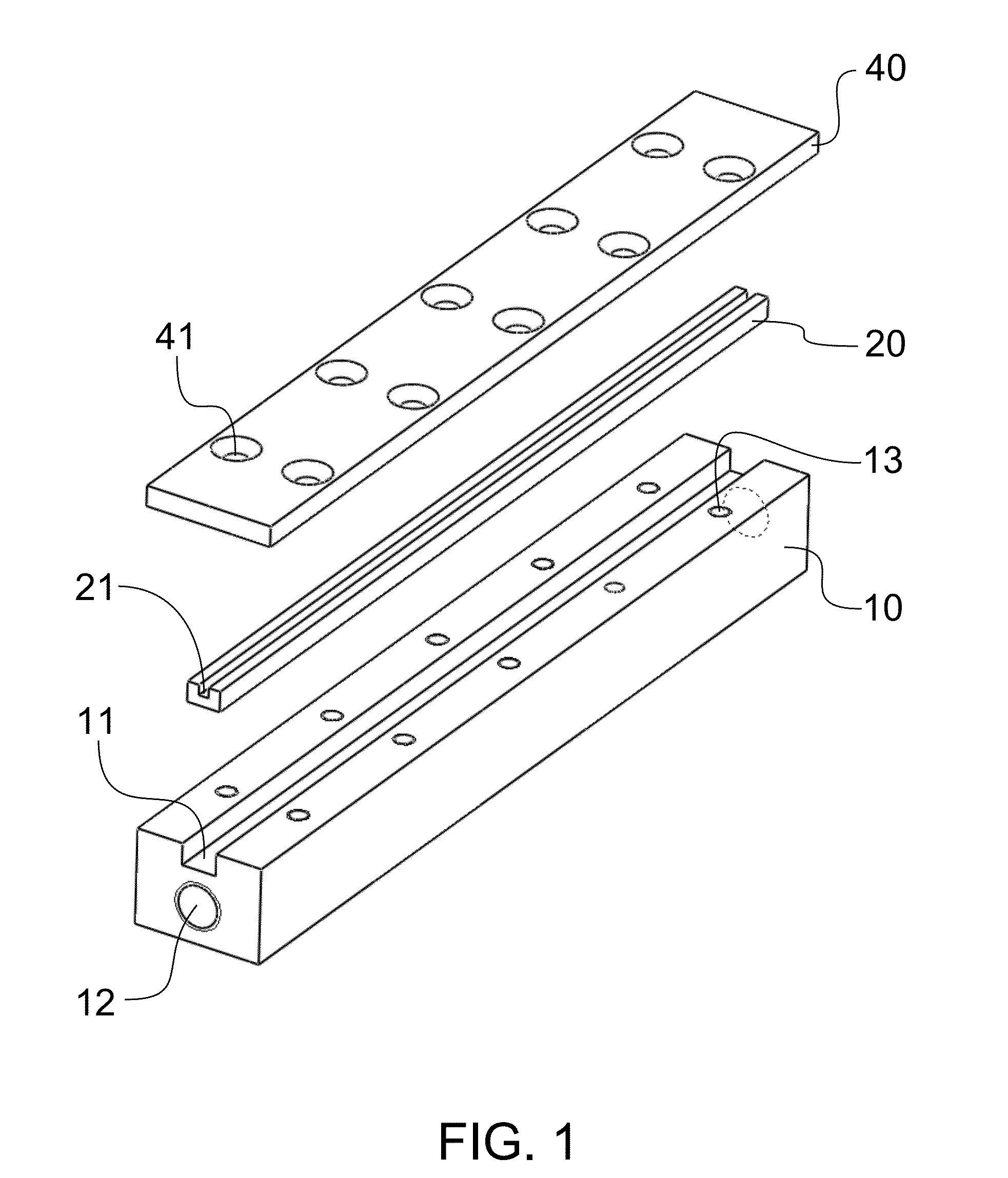
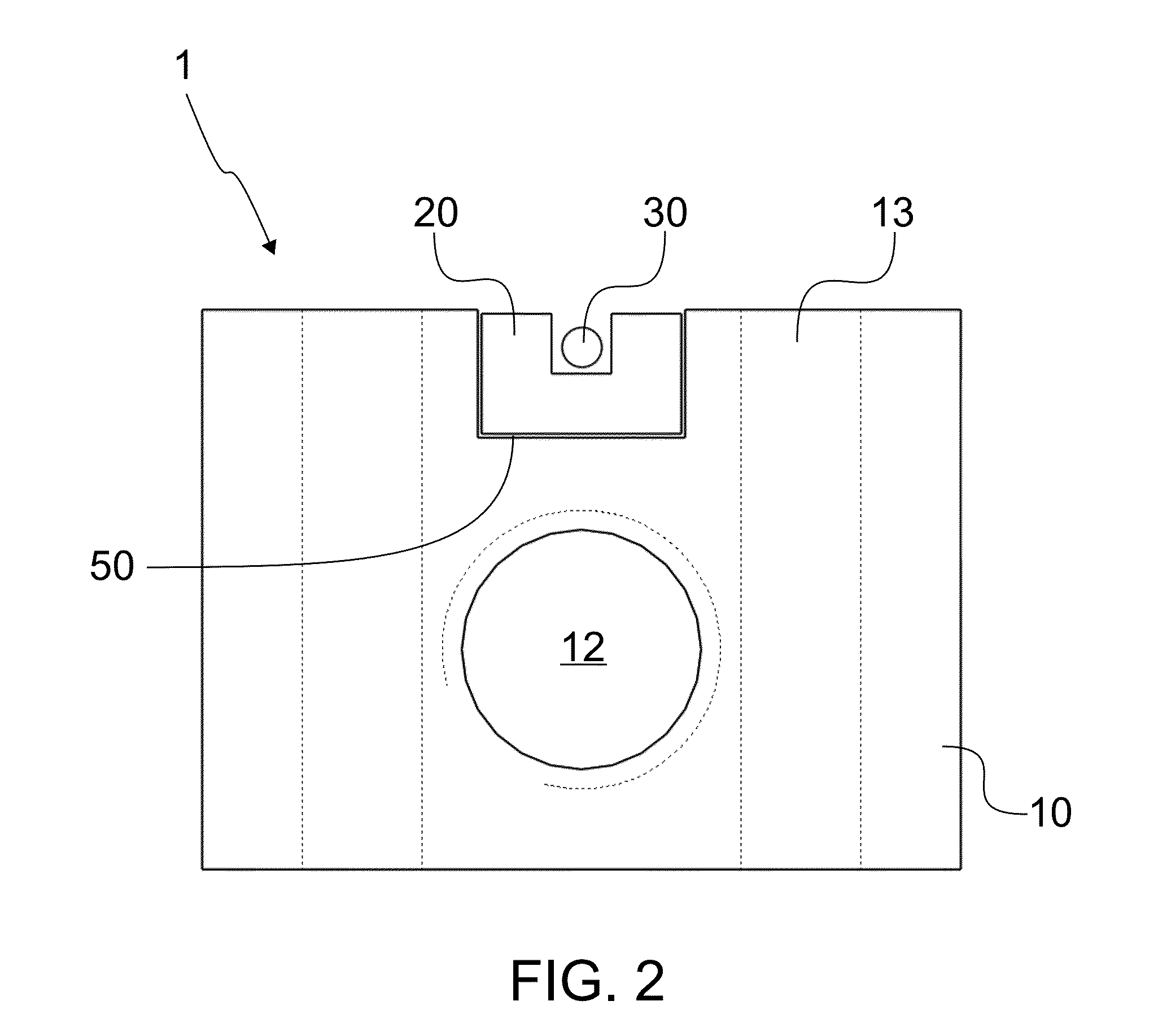
[0019]As can be seen in FIGS. 1 and 2, the fiber optic component packaging 1 according to the invention comprises a first support member 10 having a first coefficient of thermal expansion k1. The packaging also comprises a second support member 20 having a second coefficient of thermal expansion k2. A fiber optic component 30, such as an optical fiber, is mounted to a longitudinal groove 21 of the second support member 20 and preferably attached thereto by means of adhesive applied to both ends of the groove 21. In other words, the second support member 20 acts as a sub-mount for the fiber optic component 30. The second support member 20 is further mounted to a corresponding longitudinal and rectangular groove 11 of the first support member 10.

[0020]The attachment of the second support member 20 to the first support member 10 is done resiliently in order to minimize the transfer of thermal expansion induced strain of the first support member 10 to the second support member 20. The r...


PUM

PropertyMeasurementUnit
Flexibilityaaaaaaaaaa
Areaaaaaaaaaaa
Wavelengthaaaaaaaaaa

Abstract

The present invention provides a packaging for a fiber optic component, such as an optical fiber, wherein the heating induced strain to the fiber optic component is minimized, where the packaging comprises a first support member having a first coefficient of thermal expansion (k1). The packaging further comprises a second support member, which is resiliently mounted to the first support member for minimizing transfer of thermal expansion induced strain of the first support member to the second support member. The second support member comprises a longitudinal groove open at least on one side of the second support member for receiving a fiber optic component, wherein the second support member has a tensile strength considerably higher than that of the fiber optic component. The second support member has a second coefficient of thermal expansion (k2) substantially smaller than the first coefficient of thermal expansion (k1), wherein the first support member is adapted to exchange heat induced by free-space radiation. The second support member is made of material, such as quartz, which is transparent to the wavelengths used in the component.

Description

FIELD OF INVENTION[0001]The present invention relates to packaging of fiber optic components. More precisely, the invention relates to an optical fiber packaging and manufacturing method according to the preamble portions of claims 1 and 11.BACKGROUND ART[0002]Fiber lasers have gained market share from more conventional laser sources in various industrial applications, where high optical power levels are required to process a work piece. The rising popularity of fiber lasers is due to their high efficiency, high beam quality, and low need of maintenance.[0003]In order for the fiber laser to function reliably as a whole, the fiber optic components thereof, such as pump or signal couplers, must be constructed in a robust manner. When inside of a high-power fiber laser, the fiber optic components may be subject to high optical radiation fluencies. Most of the optical radiation is designed to be guided by the glass structure of the component when operated in the forward direction. Howev...

Claims


Application Information

Patent Timeline
IPC IPC(8): G02B6/44G02B6/46
CPCG02B6/4439G02B6/46G02B6/4429G02B6/0218H01S3/06704Y10T29/49826G02B6/2558
Inventor SALOKATVE, ARTO
Owner ROFIN SINAR LASER
Why Eureka
Try Eureka