Sputtering process

Inactive Publication Date: 2013-12-05
VON ARDENNE ANLAGENTECHNIK GMBH
View PDF3 Cites 6 Cited by
  • Summary
  • Abstract
  • Description
  • Claims
  • Application Information

AI Technical Summary

Benefits of technology

The patent describes a process called HiPIMS (high-purity impact molecular sputtering) for improving the efficiency of sputtering processes used in various industrial applications. The process involves modifying the distribution of target components in a way that increases the sputtering rate and improves the uniformity of the dispersion of the target component in the removal surface. This results in increased admixture concentration, reduced impurity concentration, and improved performance of the sputtering process. The use of HiPIMS can also reduce the cost of target production and allow for the use of a wider range of target components. The technical effects of the process include increased sputtering rate, improved uniformity of dispersion, and reduced impurity concentration. Additionally, the process utilizes the principle of impulse transfer to increase sputtering efficiency and can also enhance the sublimation of the target component.

Problems solved by technology

Similarly, however, a target component may only be technologically required, so that it is not desired as a layer component, or only in such a proportion that the nature of the layer is not influenced.

Method used


Image

  • Sputtering process
  • Sputtering process

Examples


Embodiment Construction

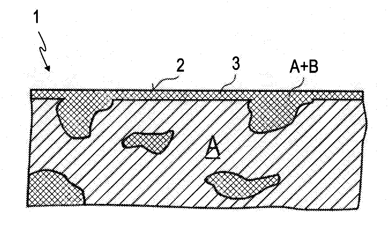
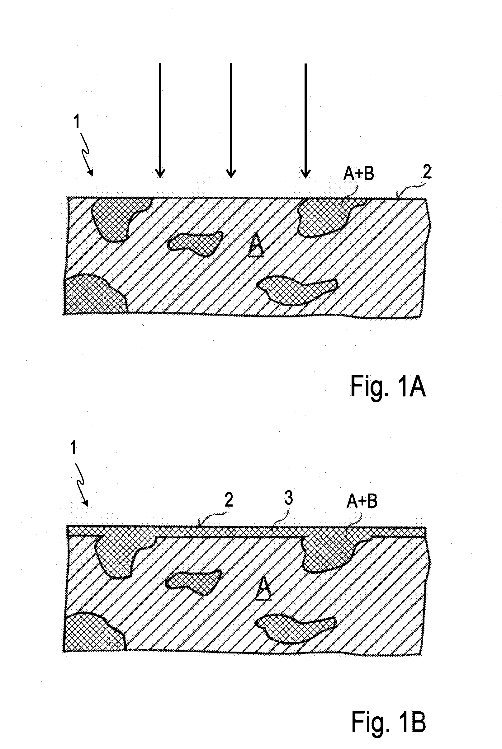
[0028]In FIG. 1A, the distribution of the target component A, for example carbon, as the layer-forming target component, and of the target component B in a region near the surface to be atomized of the mixed target 1 is represented. Target component A forms the essential part of the target material. Distributed in the matrix of the target component A are regions in which there is a mixture of the target components A and B. In the exemplary embodiment, these regions are of tungsten carbide, since tungsten was admixed as target component B in the form of tungsten carbide during target production with a specific grain size distribution with a lower limit, or else was redistributed or segregated in the thermally activated sintering processes.

[0029]In this connection, the surface of the mixed target 1 is exposed to an HiPIMS process (represented by arrows directed toward the surface), wherein the proportions of the HiPIMS pulse sequence in alternation with DC or MF sputter sequences have...


PUM

PropertyMeasurementUnit
Massaaaaaaaaaa
Distributionaaaaaaaaaa
Sublimation pointaaaaaaaaaa

Abstract

In a process for coating a substrate, the substrate is arranged opposite a removal surface of a target and the coating material is atomized by sputtering under an inert or reactive-gas-containing process gas and deposited on the substrate. The coating takes place from a mixed target with at least one target component A and a target component B. At the beginning of the sputtering process, the distribution of the target components A and B in a superficial target layer of the removal surface is modified by high-power impulse magnetron sputtering.

Description

CROSS REFERENCE TO RELATED APPLICATIONS [0001]This application claims priority of German application No. DE 10 2012 209 293.5 filed on Jun. 1, 2012, the entire contents of which is hereby encorporated by reference herein.BACKGROUND ART [0002]The invention relates generally to a sputtering process for depositing a layer on a substrate.[0003]In sputtering, a substrate to be coated is arranged opposite a removal surface of a target under a vacuum in an inert or reactive-gas-containing process gas and the coating material is atomized by means of magnetron sputtering and deposited on the substrate. For this purpose, a plasma is ignited between the substrate to be coated and a cathode and the positive charge carriers thereof remove the upper layers of a target surface by what is known as the sputtering effect (sputtering, i.e. ejection of atoms from the solid surface induced by ion bombardment). A wide range of materials can be sputtered, without or with the presence of reactive gas, and ...

Claims


Application Information

Patent Timeline
IPC IPC(8): C23C14/35
CPCC23C14/352C23C14/3414C23C14/3485C23C14/3492H01J37/3467
Inventor NEIDHARDT, JOERGABRASONIS, GINTAUTAS
Owner VON ARDENNE ANLAGENTECHNIK GMBH
Why Eureka
Try Eureka