Photovoltaic power system with generation modules

a technology of photovoltaic power system and generation module, which is applied in the direction of a dc network circuit arrangement, semiconductor device, etc., can solve the problems of risk of electric shock and the inability to automatically reduce the output voltage to zero vol

Inactive Publication Date: 2013-12-05
DELTA ELECTRONICS INC
View PDF2 Cites 21 Cited by
  • Summary
  • Abstract
  • Description
  • Claims
  • Application Information

AI Technical Summary

Benefits of technology

[0009]An object of the invention is to provide a photovoltaic power system to solve the above-mentioned problems. Accordingly, the photovoltaic power system includes a plurality of generation modules and a main communication apparatus. The generation modules are electrically connected in series. Each of the generation modules has a photovoltaic panel assembly, a switch integrated apparatus, and a junction apparatus. The photovoltaic panel assembly has a plurality of photovoltaic panels electrically connected in series. The switch integrated apparatus has a control unit and a switch unit. The switch unit is electrically connected to the control unit. The junction apparatus is electrically connected between the photovoltaic panel assembly and the switch integrated apparatus and configured to collect electricity generated from the photovoltaic panels and configured to deliver collected electricity to an output terminal of the generation module. The main communication apparatus is connected to the switch integrated apparatus of the corresponding generation module and configured to turn on or turn off the switch unit according to magnitude of an output voltage of the corresponding output terminal, thus controlling continuously delivering electricity or discontinuously delivering electricity generated from the photovoltaic panels.

Problems solved by technology

Therefore, the risk of electric shock will occur due to the extremely large DC output voltage.
Speaking of the present photovoltaic power systems, the output voltage cannot be automatically reduced to zero volt when the fire accident occurs.

Method used


Image

  • Photovoltaic power system with generation modules
  • Photovoltaic power system with generation modules
  • Photovoltaic power system with generation modules

Examples


first embodiment

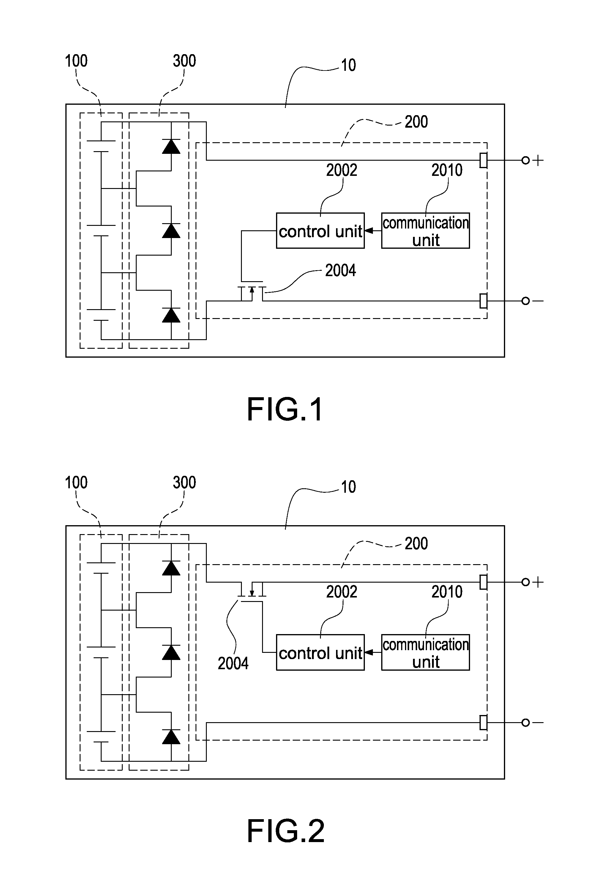
[0033]Reference is made to FIG. 1 which is a schematic circuit block diagram of a photovoltaic generation module according to the present disclosure. The generation module 10 includes a photovoltaic panel assembly 100, a switch integrated apparatus 200, and a junction apparatus 300. The photovoltaic panel assembly 100 has a plurality of photovoltaic panels (not labeled) electrically connected in series. In this embodiment, the amount of the photovoltaic panels is three. The switch integrated apparatus 200 has a control unit 2002, a switch unit 2004, and a communication unit 2010. In this embodiment, the switch unit 2004 can be a metal-oxide-semiconductor field-effect transistor (MOSFET), but not intended to limit the scope of the disclosure. The junction apparatus 300 is electrically connected between the photovoltaic panel assembly 100 and the switch integrated apparatus 200 to collect electricity generated from the photovoltaic panels and to deliver collected electricity to an out...

seventh embodiment

[0040]Reference is made to FIG. 7 which is a schematic circuit block diagram of the photovoltaic generation module according to the present disclosure. The generation module 20 includes a photovoltaic panel assembly 100, a power conversion unit 400, a junction apparatus 300, a control unit 500, and a communication unit 600. The photovoltaic panel assembly 100 has a plurality of photovoltaic panels (not labeled) electrically connected in series. In this embodiment, the amount of the photovoltaic panels is three. The power conversion unit 400 has a switch element 402. The junction apparatus 300 is electrically connected between the photovoltaic panel assembly 100 and the power conversion unit 400 to collect electricity generated from the photovoltaic panels and to deliver collected electricity to an output terminal of the generation module 20. The communication unit 600 is electrically connected to the control unit 500 to provide wired or wireless communications to the control unit 50...

ninth embodiment

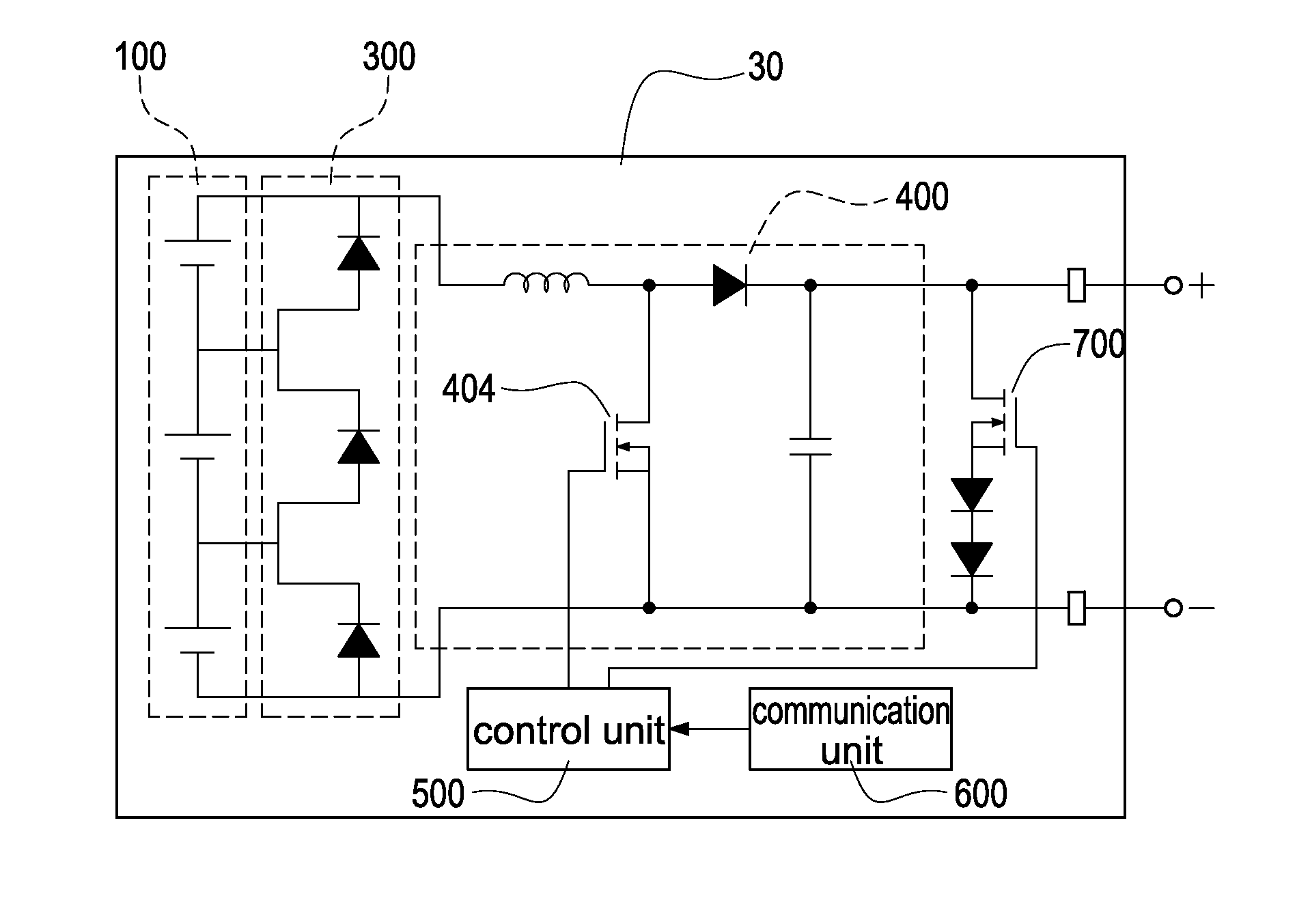
[0042]Reference is made to FIG. 9A which is a schematic circuit block diagram of the photovoltaic generation module according to the present disclosure. The generation module 30 includes a photovoltaic panel assembly 100, a switch unit 700, a power conversion unit 400, a junction apparatus 300, a control unit 500, and a communication unit 600. The photovoltaic panel assembly 100 has a plurality of photovoltaic panels (not labeled) electrically connected in series. In this embodiment, the amount of the photovoltaic panels is three. The power conversion unit 400 has a switch element 402. The junction apparatus 300 is electrically connected between the photovoltaic panel assembly 100 and the power conversion unit 400 to collect electricity generated from the photovoltaic panels and deliver collected electricity to an output terminal of the generation module 30. The communication unit 600 is electrically connected to the control unit 500 to provide wire or wireless communications to the...


PUM


Abstract

A photovoltaic power system includes a plurality of generation modules and a main communication apparatus. Each generation module has a photovoltaic panel assembly, a switch integrated apparatus, and a junction apparatus. The photovoltaic panel assembly has a plurality of photovoltaic panels electrically connected in series. The switch integrated apparatus has a control unit and a switch unit. The junction apparatus is electrically connected between the photovoltaic panel assembly and the switch integrated apparatus to collect electricity generated from the photovoltaic panels and deliver collected electricity to output terminals of the photovoltaic power generation module. The main communication apparatus is connected to the switch integrated apparatuses to turn on or turn off the switch unit according to magnitude of the output voltage, thus controlling continuously delivering electricity or discontinuously delivering electricity generated from the photovoltaic panels.

Description

[0001]This application is based on and claims the benefit of Taiwan Application No. 101119253 filed May 30, 2012 the entire disclosure of which is incorporated by reference herein.BACKGROUND OF THE INVENTION[0002]1. Field of the Invention[0003]The present disclosure relates generally to a photovoltaic power system with generation modules, and more particularly to a photovoltaic power system with generation modules that is controlled to continuously deliver electricity or discontinuously deliver electricity generated from photovoltaic panels by turning on or turning off a switch unit.[0004]2. Description of Prior Art[0005]The solar photovoltaic system provides a photovoltaic conversion to generate a DC power through the solar cell panels. Afterward, the DC power is converted into an AC power through a power conditioner to supply to a load or the converted AC power is grid-connected to an AC utility power through the utility grid bus. The solar photovoltaic system can be broadly divid...

Claims


Application Information

Patent Timeline
Patent Type & Authority Applications(United States)
IPC IPC(8): H02J1/00
CPCH01L31/02021H02J2300/24H02J3/381Y02E10/56
Inventor HUANG, CHI-HSINGLI, SHENG-HUA
Owner DELTA ELECTRONICS INC
Why Eureka
Try Eureka