Control apparatus for semiconductor switches of an inverter, and method for driving an inverter

Active Publication Date: 2013-12-05
ROBERT BOSCH GMBH
View PDF3 Cites 5 Cited by
  • Summary
  • Abstract
  • Description
  • Claims
  • Application Information

AI Technical Summary

Benefits of technology

[0010]One idea of the present invention is to provide a control apparatus for semiconductor switches of an inverter in an electrically operated vehicle, which control apparatus can implement a reliable and robust rapid or emergency discharge. In this case, the commutation current through a half-bridge branch of the inverter is determined by detecting and evaluating the profile of a voltage signal across the half-bridge branch or one of the semiconductor switches. Feedback of the detected commutation current can be used, on the one hand, to carry out fine adjustment of the discharge circuit and, on the other hand, to implement different diagnostic and monitoring mechanisms for checking and ensuring the proper functionality of the discharge circuit. In this case, the rapid or emergency discharge is carried out using semiconductor switches which are present in the inverter anyway and at which the required voltage signals can also be tapped off. This dispenses with the need to provide dedicated emergency discharge circuits or diagnostic circuits, which can entail a considerable saving in terms of costs and installation space.
[0011]One advantage of the invention is that an inverter which is configured with a control apparatus according to the invention and comprises a multiplicity of bridge branches each with two semiconductor switches can be driven in such a manner that one of the semiconductor switches of a particular number of bridge branches is respectively “clocked”, that is to say the drive signal consists of short drive pulses, the pulse length of which is selected to be just so short that the semiconductor switch is not yet switched to be completely conductive but rather is briefly in a transition state between the switched-off state and the conductive state. During this time, energy from the intermediate circuit capacitor can be converted into heat when a current flows through the respective semiconductor switches and the voltage in the intermediate circuit can thus be rapidly and effectively reduced. This provides the advantage that an intermediate circui

Problems solved by technology

In addition, in the event of a fault, it is necessary to rapidly and reliably discharge the DC voltag

Method used


Image

  • Control apparatus for semiconductor switches of an inverter, and method for driving an inverter
  • Control apparatus for semiconductor switches of an inverter, and method for driving an inverter
  • Control apparatus for semiconductor switches of an inverter, and method for driving an inverter

Examples


Embodiment Construction

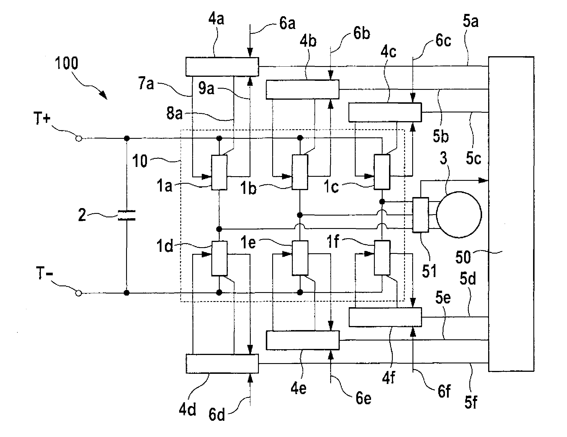
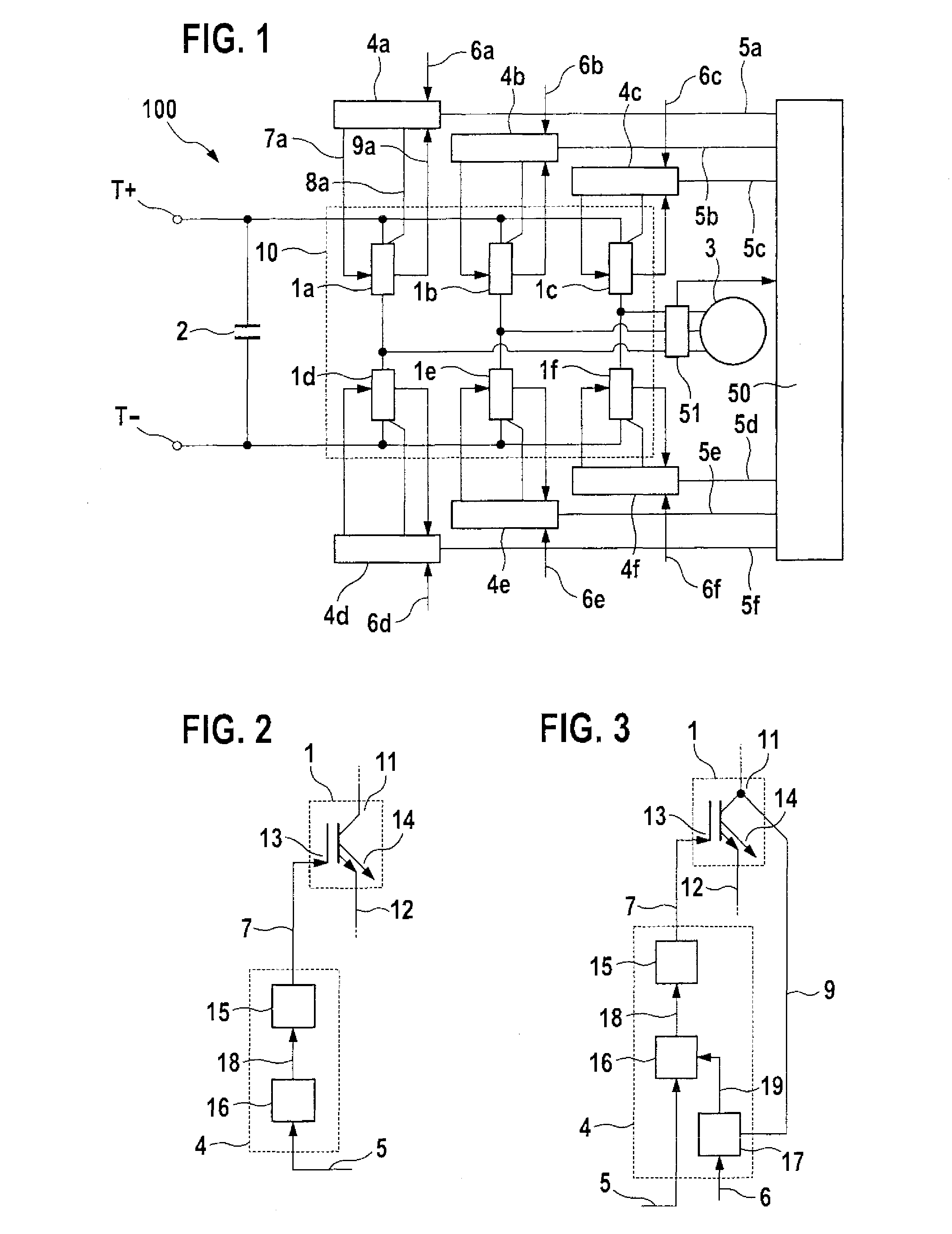
[0038]FIG. 1 shows a schematic illustration of an electrical drive system 100 of a vehicle. The electrical drive system 100 comprises two input connections T+ and T− which can be supplied with high voltage, for example by means of an energy storage device such as a high-voltage battery or traction battery of the vehicle. The input connections T+ and T− are connected to a DC voltage intermediate circuit having an intermediate circuit capacitor 2. The intermediate circuit capacitor 2 is connected, via output connections, to input connections of an inverter 10, for example a pulse-controlled inverter 10. The voltage intermediate circuit converter which is illustrated in FIG. 1 and has the intermediate circuit capacitor 2 and the inverter 10 is illustrated, by way of example, in the form of a three-phase converter, that is to say the inverter 10 comprises three bridge branches each with two semiconductor switches. The first bridge branch comprises, for example, the semiconductor switche...


PUM


Abstract

A control apparatus for driving a semiconductor switch of an inverter. A drive circuit generates a driver signal on the basis of a switching signal generated by a control regulation system of the inverter. A driver circuit which is coupled between the drive circuit and a control input of the semiconductor switch is configured to receive the driver signal and to generate, on the basis of the driver signal, a control signal which drives the semiconductor switch. The control signal is fed into the control input of the semiconductor switch. A regulation circuit is coupled to the drive circuit and is configured to detect a voltage signal dependent on the voltage across the semiconductor switch, to generate a regulation signal which is dependent on the voltage signal and is intended to regulate the driver signal, and to feed the regulation signal into the drive circuit.

Description

BACKGROUND OF THE INVENTION[0001]The invention relates to a control apparatus for semiconductor switches of an inverter and to a method for driving an inverter, in particular for operating an inverter in a rapid discharge mode.[0002]Electric and hybrid vehicles often have power-electronic circuit components in the drive system between the traction battery and the electrical machine which are generally constructed as voltage intermediate circuit converters. In this case, a DC voltage intermediate circuit is used as a coupling element between the traction battery and an inverter which can be driven to transmit electrical power from the DC voltage intermediate circuit to the electrical machine.[0003]Inverters may be in the form, for example, of a full-bridge circuit having a number of bridge branches with two semiconductor switches each. In this case, those semiconductor switches of the bridge branches which are connected to a first output connection of the DC voltage intermediate circ...

Claims


Application Information

Patent Timeline
IPC IPC(8): G05F1/10
CPCG05F1/10H03K17/165
Inventor EBERLEIN, EDWINSCHOENKNECHT, ANDREAS
Owner ROBERT BOSCH GMBH
Why Eureka
Try Eureka