Unit magnification large-format catadioptric lens for microlithography

a catadioptric lens, large-format technology, applied in the field of microlithography, can solve the problems of degrading not being able to alter magnification, etc., and achieve the effect of minimizing pattern overlay errors, allowing for very small magnification of the system, and reducing focus and/or image quality

Inactive Publication Date: 2013-12-05
VEECO INSTR
View PDF7 Cites 14 Cited by
  • Summary
  • Abstract
  • Description
  • Claims
  • Application Information

AI Technical Summary

Benefits of technology

[0015]One benefit of the small amount of non-telecentricity is that shifting focus at the object and image planes by equal amounts in the same direction along the optic axis allows the magnification of the system to be very slightly altered. This is advantageous because pattern overlay errors can be minimized thereby. In the case of a perfectly telecentric optical system, it is not possible to alter the magnification by adjusting the optics within without degrading focus and / or image quality.

Problems solved by technology

In the case of a perfectly telecentric optical system, it is not possible to alter the magnification by adjusting the optics within without degrading focus and / or image quality.

Method used


Image

  • Unit magnification large-format catadioptric lens for microlithography
  • Unit magnification large-format catadioptric lens for microlithography
  • Unit magnification large-format catadioptric lens for microlithography

Examples


first example embodiment

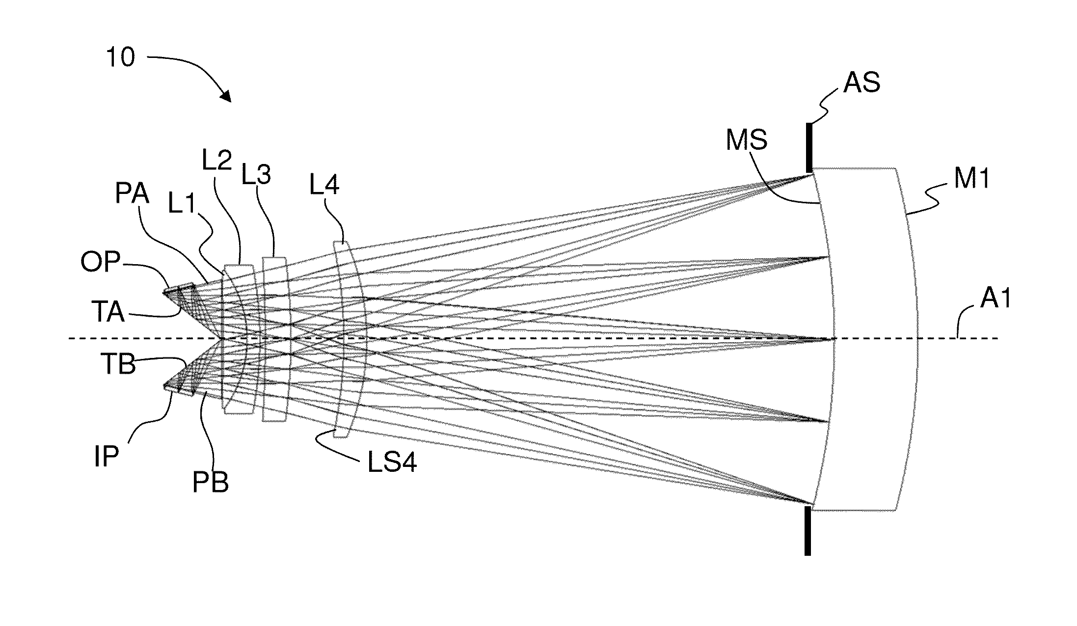
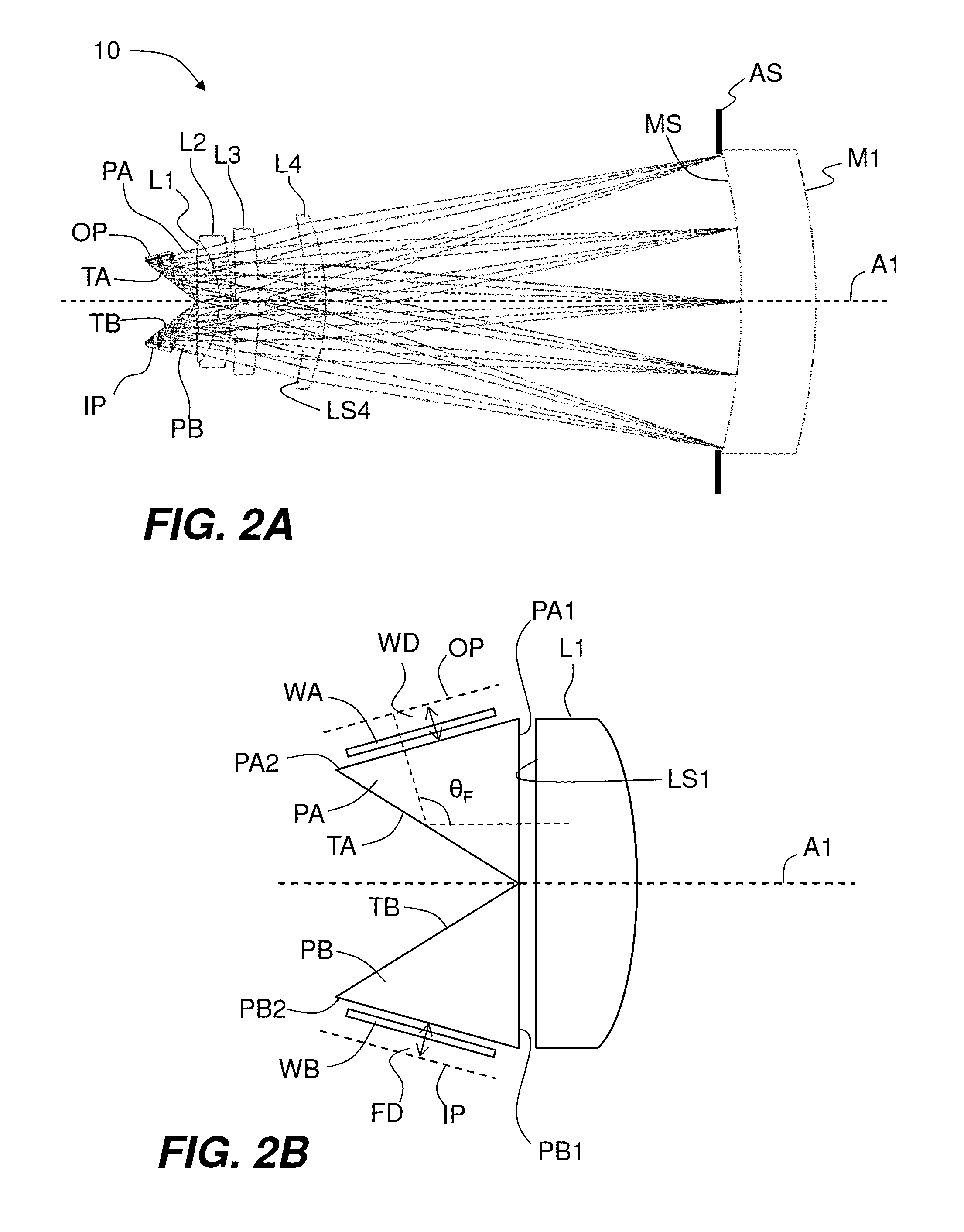
[0078]FIG. 2A is a diagram of a first example embodiment of a 1× modified Wynn-Dyson catadioptric optical system (“system”) 10 according to the disclosure. The system 10 includes a primary concave mirror M1 centered on an optical axis A1. The minor M1 has a mirror surface MS. An aperture stop AS is located at mirror surface MS. The system 10 includes four refractive lens elements L1 through L4 arranged along axis Al on the concave side of minor M1 and axially spaced apart from mirror surface MS. The system 10 includes separation fold prisms (“prisms”) PA and PB that each reside adjacent lens L1 but on opposite sides of optical axis A1. The prisms PA and PB have respective TIR surfaces TA and TB that serve to fold system 10 so that an image plane IP and an object plane OP do not overlap on axis Al.

[0079]FIG. 2B is a close-up view of prisms PA and PB and the respective object and image planes OP and IP. The prism PA includes a planar surface PA1 adjacent a lens surface LS1 of lens ele...

second example embodiment

[0117]FIG. 11A is similar to FIG. 2A and illustrates a second example embodiment of system 10 that includes three air-spaced refractive lens elements L1, L2 and L3. The system 10 is configured to provide a six-die format at the i-line LED or GHI-s spectral bands. The field size is 102 mm×52 mm and has a transmission of 75% at the i-line wavelength. The working distance WD=6 mm. The system 10 includes the aforementioned windows WA and WB that in an example are 1 mm thick and made of fused silica. The fold angle θF is 103 degrees. The unfolded length is 1,417.5 mm. The aperture stop AS has a clear aperture of 749.8 mm, and primary minor M1 has a clear aperture of 780 mm and is 175 mm thick. The prism path length is 107 mm. The lens L3 has a concave surface LS3 that is aspheric. Minor surface MS is also aspheric. The NA=0.32. The back focus distance FD is essentially the same as in the working distance WD due to the system symmetry.

[0118]Table 5 sets forth an example lens-design prescr...


PUM


Abstract

A unit magnification Wynn-Dyson lens for microlithography has an image field sized to accommodate between four and six die of dimensions 26 mm×36 mm. The lens has a positive lens group that consists of either three or four refractive lens elements, with one of the lens elements being most mirror-wise and having a prism-wise concave aspheric surface. Protective windows respectively reside between object and image planes and the corresponding prism faces. The lens is corrected for at least the i-line LED wavelength spectrum or similar LED-generated wavelengths.

Description

CLAIM OF PRIORITY[0001]This application claims the benefit of priority under 35 U.S.C. §119(e) of U.S. Provisional Application Ser. No. 61 / 653,020, filed on May 30, 2012, which is incorporated herein by reference.FIELD[0002]The disclosure relates to lenses for microlithography, and in particular to a unit-magnification, catadioptric lens for microlithography that has a large field for accommodating multiple die.BACKGROUND ART[0003]Photolithography tools are used to print small features on semiconductor (e.g., silicon) wafers in the fabrication of integrated circuits (ICs). Photolithography tools are also used for back-end processes that involve, for example, forming patterns to define layer interconnects. Layer interconnects provide electrical power to drive the IC. The photolithography tools are also used in the back-end process to pattern metal pathways of the high-speed communication bus used to transmit control logic and data input / output (I / O) of the IC.[0004]In the past two de...

Claims


Application Information

Patent Timeline
Patent Type & Authority Applications(United States)
IPC IPC(8): G02B17/08
CPCG02B17/08G03F7/70225G02B5/04G02B17/06G02B27/02G03B21/14G03B27/02G03B27/42G03F7/20
Inventor STITES, DAVID G.
Owner VEECO INSTR
Why Eureka
Try Eureka