

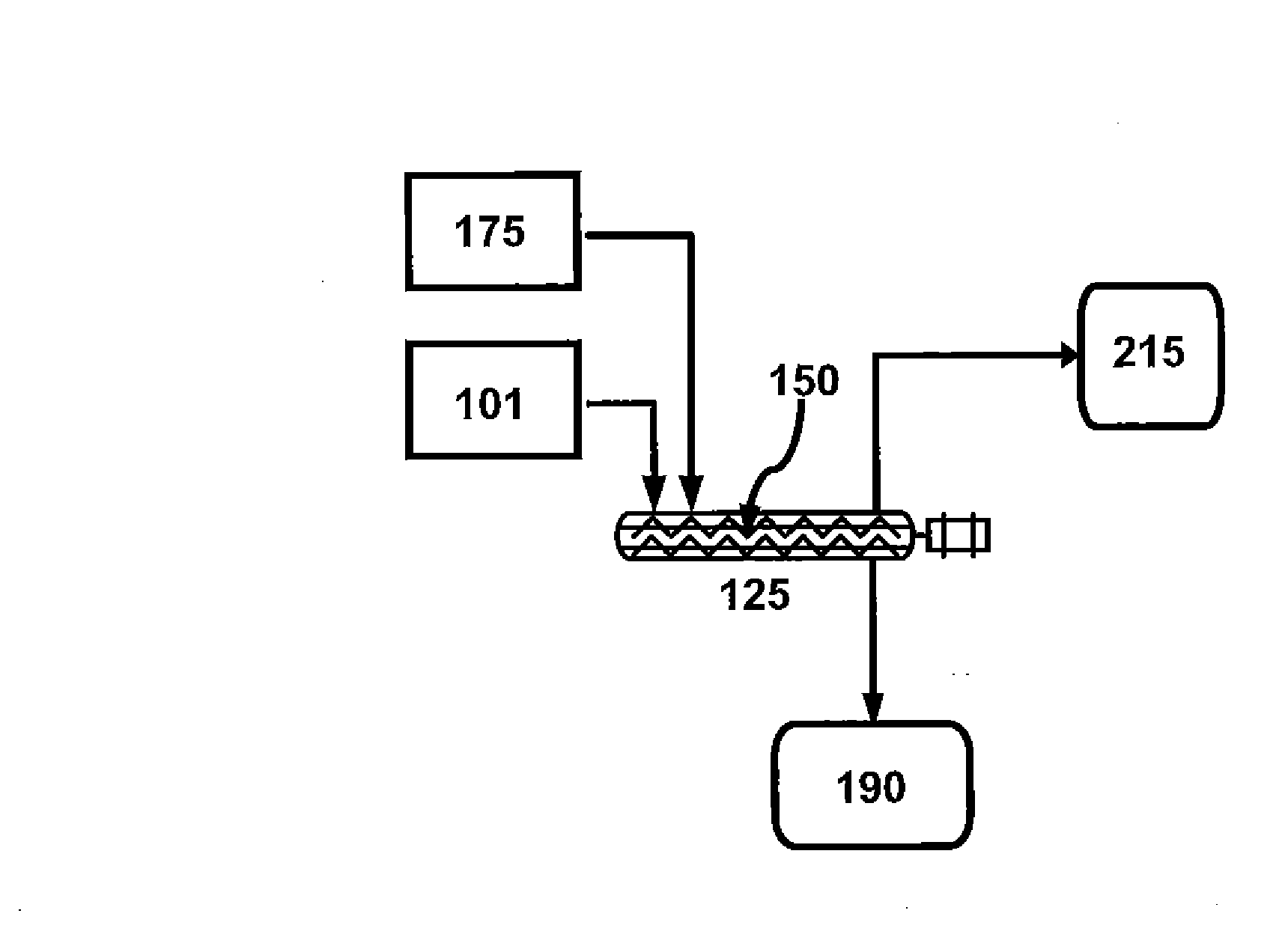
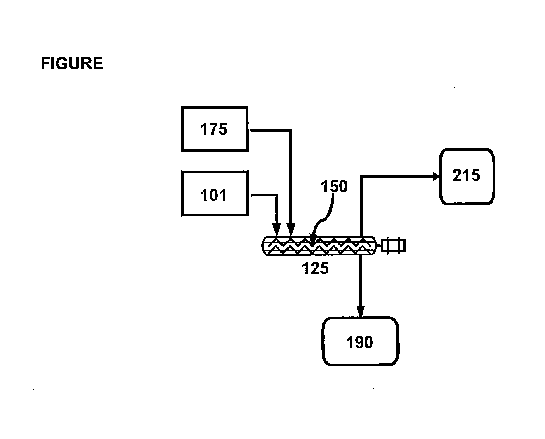
Catalytic biomass pyrolysis in an auger reactor
a biomass pyrolysis and auger reactor technology, applied in the direction of mechanical conveying coke ovens, biofuels, products, etc., can solve the problems of acidic and thermally unstable bio-oil, and achieve the effect of reducing the temperature required for pyrolysis and increasing the rate of pyrolysis
- Summary
- Abstract
- Description
- Claims
- Application Information
AI Technical Summary
Benefits of technology
Problems solved by technology
Method used
Image

Examples
example 1
[0035]Either micro-algal or lignin biomass was dried at 70° C. for 12 hours, and then pyrolyzed with and without zeolite catalyst in inert (He) atmosphere. Pyrolysis was conducted at 475° C. pyrolysis temperature, heating rate ˜10,000° C. / s and a 5:1 catalyst ratio (when used). Vapors were analyzed by gas chromatography / mass spectrometry (GC / MS). Char was measured by gravimetric difference. All yields are on a mass basis.
[0036]The data (see Tables 1 and 2) show a greater than 60% yield of condensable vapors from both micro-algal (Table 1) and lignin (Table 2) biomass in un-catalyzed pyrolysis and 50% or greater yield during catalyzed pyrolysis. Adding a zeolite catalyst improved yield of hydrocarbons in the vapor phase, while also increasing char yield.
TABLE IYield of pyrolysis products from dried, whole microalgae.Yield %,Yield %,Productno catalystzeolite catalystNoncondensable gas*617Char*1928Condensable vapors*7455Hydrocarbons in vapor**944*Yield based on total biomass**Yield bas...
PUM
| Property | Measurement | Unit |
|---|---|---|
| temperature | aaaaa | aaaaa |
| pressure | aaaaa | aaaaa |
| temperature | aaaaa | aaaaa |
Abstract
Description
Claims
Application Information