
Scanner photometer & methods

Active Publication Date: 2013-12-12
LGC GENOMICS LLC
View PDF1 Cites 1 Cited by
  • Summary
  • Abstract
  • Description
  • Claims
  • Application Information

AI Technical Summary

Benefits of technology

This patent text describes how to use a multi-dye scanning photometer to measure different fluorescences at the same time. The text describes three main types of measurements: colocalization, consensing, and confocalization. Colocalization means getting independent measurements at the same place. Consensing means using only one detector to detect two fluorescences. Confocalization means aligning the detector with the sample in the same way as if it was a microscope. These techniques help to get more accurate and reliable data from the sample.

Problems solved by technology

Optical scanning heads, more particularly photometers, include components, such as photomultiplier tubes (PMTs), which are susceptible to mechanical vibration.
With increased processing throughput via the use of continuously spooled array tape and the like, use of a stationary photometer has become impractical, however, any inconsistency in the relative position between the scanning photometer and each target of a series of targets, due to any reason, can cause significant differences in the quality of output data.
Repeatability of data acquisition conditions is highly valued, and in the context of reduced specimen / target volumes for scanning, and with regard to the high volume throughput available with array tapes, repeatability, reliability and precision is an increasing challenge.

Method used


Image

  • Scanner photometer & methods
  • Scanner photometer & methods
  • Scanner photometer & methods

Examples


Embodiment Construction

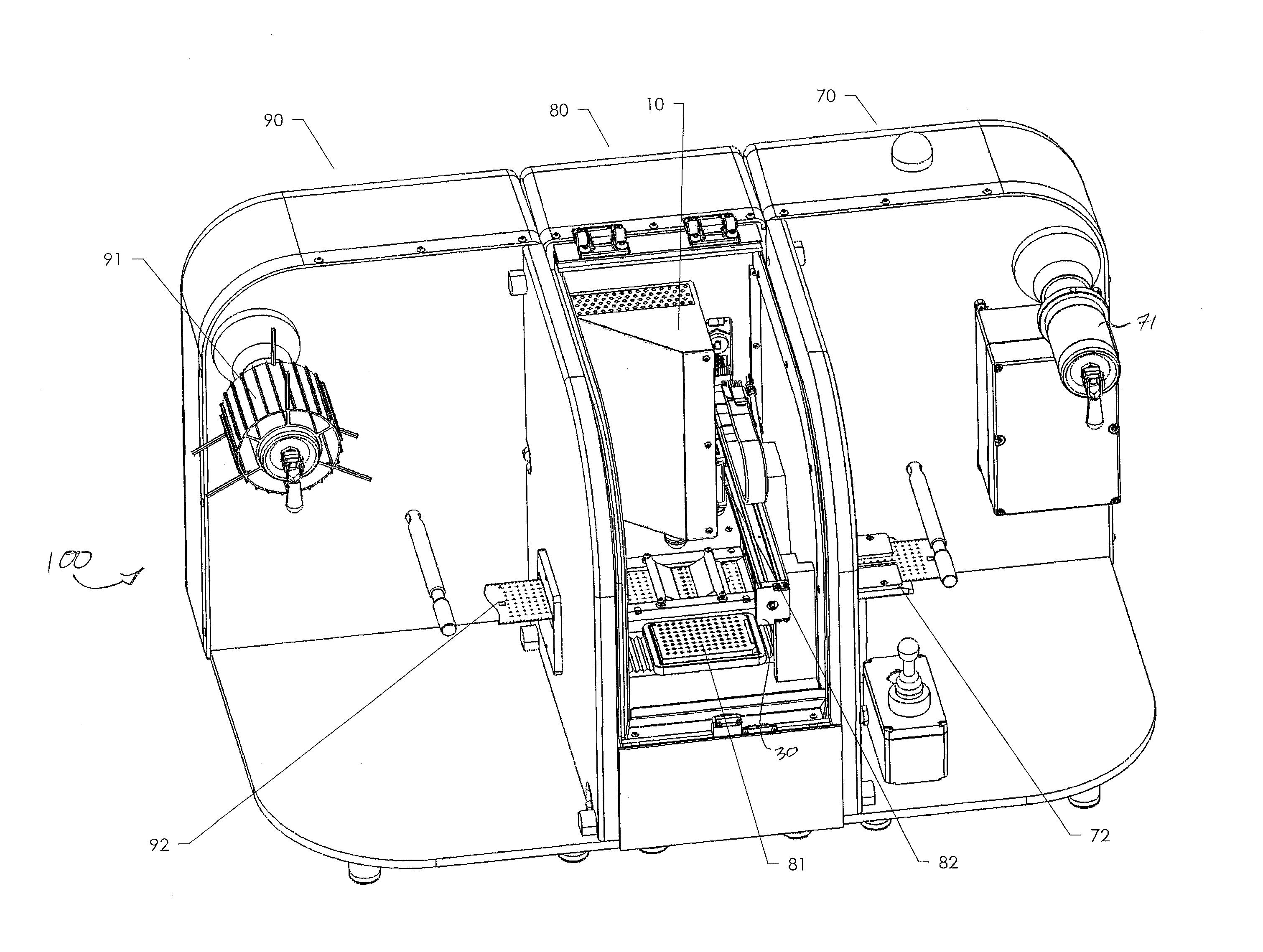
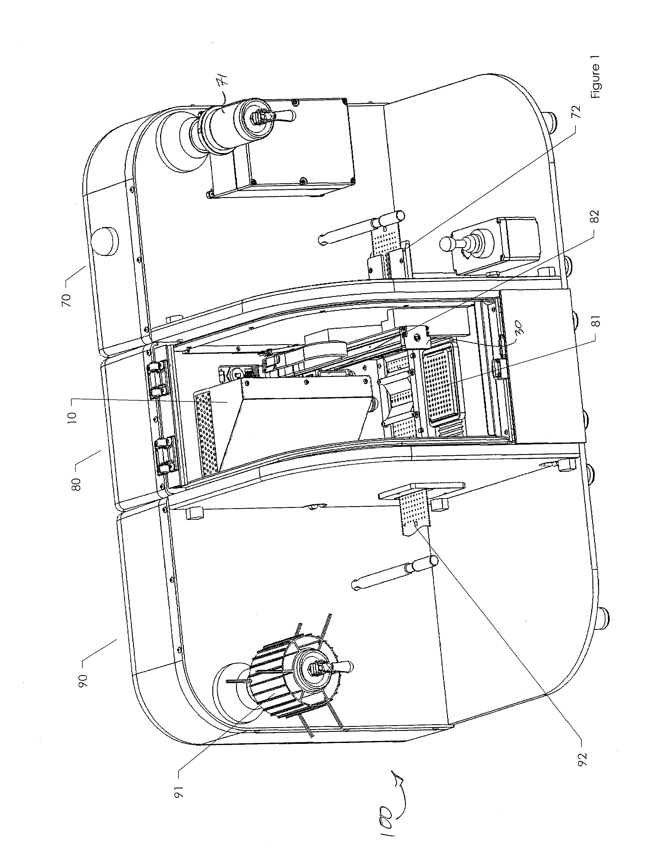
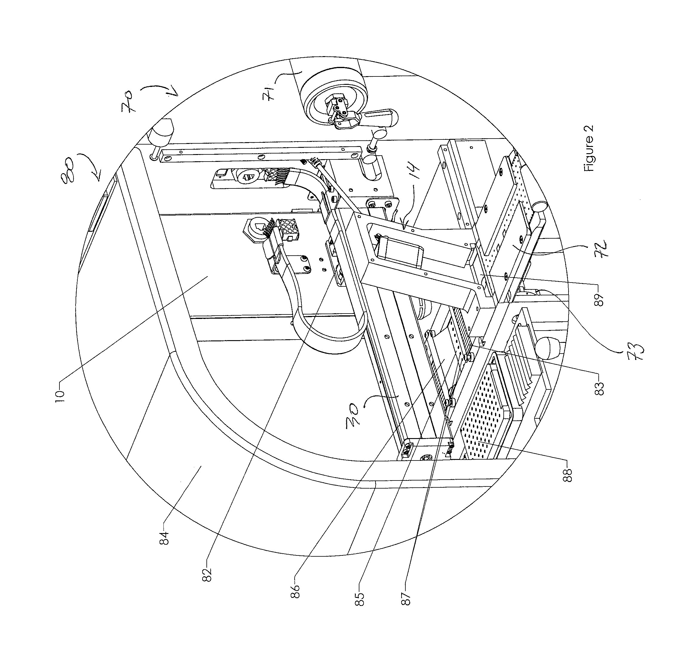
[0018]The following description immediately proceeds with general reference to FIGS. 1 & 2, wherein a preferred, non-limiting scanning photometer apparatus is generally depicted, and thereafter with particular reference to FIGS. 3 & 4 wherein an optical reader or optical reader head of the subject apparatus is depicted. Finally, reference is made to FIG. 5 with regard to preferred apparatus operation.

[0019]Contextually, the apparatus of FIGS. 1 & 2 is advantageously, but not exclusively suited for high speed scanning, derived, at least in part, from the utilization of array tape (see e.g., U.S. Pat. No. 6,878,345 B1) and an automated system / process for / of handling same (see e.g., the Nexar™ array tape automation instrument by Douglas Scientific, Minnesota, USA). Moreover, while the subassembly of FIGS. 3 & 4 may be generally and fairly characterized as an optical reader head, it may be more particularly and fairly characterized as a multi-dye fluorescence photometer, having particul...


PUM


Abstract

A scanning photometer and attendant methods are provided. The scanning photometer is generally characterized by first and second fluorophore excitation sources, an objective lens, and a common emission detector for the detection of first and second fluorophore emission originating from the excitation of the fluorophores via passage of excitation energy, via an optical path of the objective lens, from the excitation sources. Excitation energy and emission energy conditioning elements are likewise provided, operatively interposed before or after the objective lens as the case may be.

Description

[0001]This is an international patent application filed under 35 U.S.C. §363 claiming priority under 35 U.S.C. §119(e) (1) to U.S. provisional pat. appl. Ser. No. 61 / 104,109, filed Oct. 9, 2008 and captioned “Scanner Photometer and Methods,” said application incorporated herein by reference in its entirety.TECHNICAL FIELD[0002]The present invention generally relates to the field of optics, more particularly, to instruments and / or methods for detecting and / or measuring light intensity or optical properties of solutions or surfaces, and more particularly still, to a scanner photometer and methods having particular utility with regard to fluorescence detection and / or quantification.BACKGROUND OF THE INVENTION[0003]The minimization of uncertainty with regard to data is universally held as advantageous. Moreover, and fundamentally, in as much as there exists a premium on precision in acquiring data, to appreciate and acknowledge uncertainty with regard to data acquisition is likewise of ...

Claims


Application Information

Patent Timeline
IPC IPC(8): G01J3/10
CPCG01J3/10G01J3/4406G01N21/645G01N21/6452G01N2021/6419G01N2021/6421G01N2021/6441G01J1/58
Inventor HAQ, ADNANULSCHOENECK, RICHARD J.
Owner LGC GENOMICS LLC
Features
  • Generate Ideas
  • Intellectual Property
  • Life Sciences
  • Materials
  • Tech Scout
  • Unparalleled Data Quality
  • Higher Quality Content
  • 60% Fewer Hallucinations
Learn More