
Tracking vehicle locations in a parking lot for definitive display on a GUI

a technology for locating vehicles and parking lots, applied in vehicle position/course/altitude control, process and machine control, instruments, etc., can solve the problems of inefficient use of labor, lost vehicle sales, and lost revenue from locating vehicles, etc., to achieve accurate and rapid locating of vehicles.

Active Publication Date: 2013-12-12
CHOWDHARY GAURAV +1
View PDF1 Cites 16 Cited by
  • Summary
  • Abstract
  • Description
  • Claims
  • Application Information

AI Technical Summary

Benefits of technology

[0021]It is an object of the invention to ameliorate or eliminate the above-mentioned disadvantages by providing, automatically, a definitive / accurate, real time, GUI display of respective positions of the multiple vehicles or other multiple objects on the map of a parking lot or mobile object facility.
[0022]An additional object of the invention is to factor in the unique characteristics of particular location technology systems and thereby significantly improve the accuracy of an object's position by assigning different priorities to respective reference points.
[0045]The invention provides the advantages of increasing the accuracy of the location estimate of the mobile object; decreasing the time required to actually physically locate the object, and reducing the burden on the user to interpret location results. In particular, the last mentioned advantage reduces the required acumen and burden of pro-activity of a user to physically locate objects.
[0046]The invention enables respective locations of groups of mobile objects crowded together to be displayed clearly, simultaneously, and in real-time. In a variety of applications, this allows users to use other displayed objects as relative landmarks when physically in the lot, locating the desired vehicle, and also prepares the user to negotiate other objects that are obstructing access to a desired object.
[0055]As mentioned above, another object of the invention is to obtain increased accuracy in the measurement of approximate respective distances of respective mobile objects from respective potentially occupiable specific sub-areas by factoring in the unique characteristics of particular location technology systems and thereby significantly improve the accuracy of an object's position by assigning different priorities to respective reference points.

Problems solved by technology

On the service side, since a service technician bills customers for time spent repairing a vehicle, any time spent locating a vehicle is lost revenue.
In the retail automotive industry, lost vehicle sales and inefficient use of labor are the costs of not locating vehicles accurately and quickly.
In fact, in both the automotive and storage and distribution industries, the problem of locating mobile objects increases in difficulty as a function of the total number of objects in inventory and the number of possible locations.
Multiple objects showing multiple images are not used often because of the difficulty of interpreting raw location information from multiple objects, simultaneously.
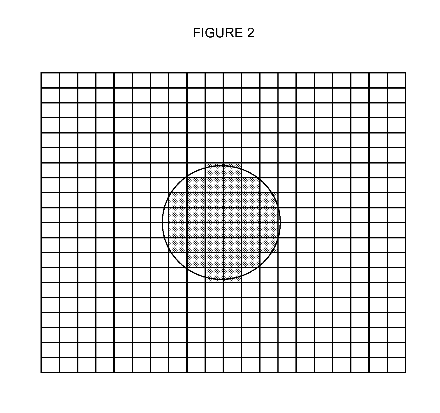
Depending on the precision of the underlying location technology, there is a resulting error radius which is expected to circumscribe the actual location of the object.
However, particularly when groups of vehicles or other objects are crowded together, the inherent location errors may result in multiple overlaps and fuzzy images which can be difficult to interpret by an observer and lead to errors in guessing actual locations which become time consuming and costly.
Alternatively, in a single object display, the user would arbitrarily choose a pallet, possibly requiring unnecessary time and work to move other pallets out of the way before being able to retrieve the pallet being sought.
However, an example of a location technology system where assigning equal priority to reference points is not favorable is a sensor network where received signal strength or power, as measured in dBm, of multiple radio signals are inputs in a trilateration algorithm.
Current approaches assign equal priority to all reference points, but because signal strength received from a reference point is intrinsically fuzzy, calculations of precise location are challenging.
Many significant obstacles are encountered: radio signals exhibit exponential decay and suffer / experience reflection, interference, attenuation or general noise.
These problems are exacerbated by the environment where the location technology system is situated, for example, variable ambient air quality—variations in air-borne particulates and in humidity.
Furthermore, at automotive dealership premises, there can be RF reflection from a vehicle's metal panels and pillars, frequency interference from WIFI and other radio / electromagnetic wave signals, and signal attenuation from physical / mechanical obstructions (e.g. walls, equipment).
This decay, coupled with imprecision arising from reflection, interference, attenuation or general noise, greatly reduce accuracy.

Method used


Image

  • Tracking vehicle locations in a parking lot for definitive display on a GUI
  • Tracking vehicle locations in a parking lot for definitive display on a GUI
  • Tracking vehicle locations in a parking lot for definitive display on a GUI

Examples


Embodiment Construction

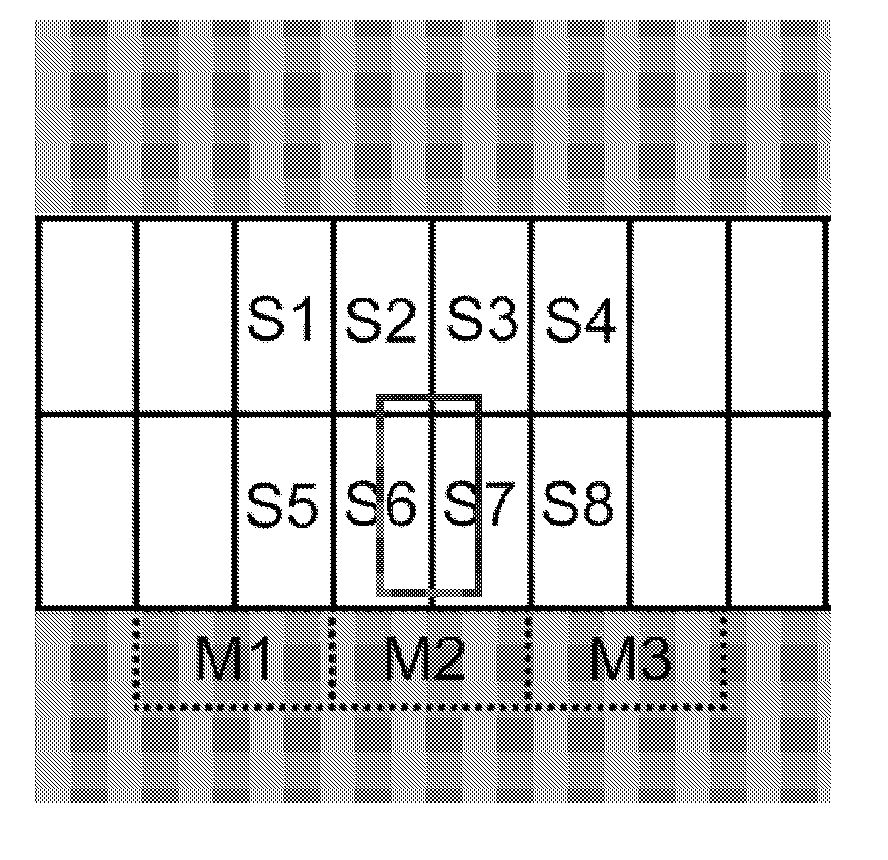
[0073]The implementation of the invention in this embodiment comprises two main stages: first, the configuration of overall lot area, sub-areas, lots and vehicles or mobile objects; and second, the placement of vehicles or mobile objects based on raw (x,y,z) coordinates as adjusted by business environment rules based on sub-area and mobile object compatibility, for definitive display on a screen at improved resolution.

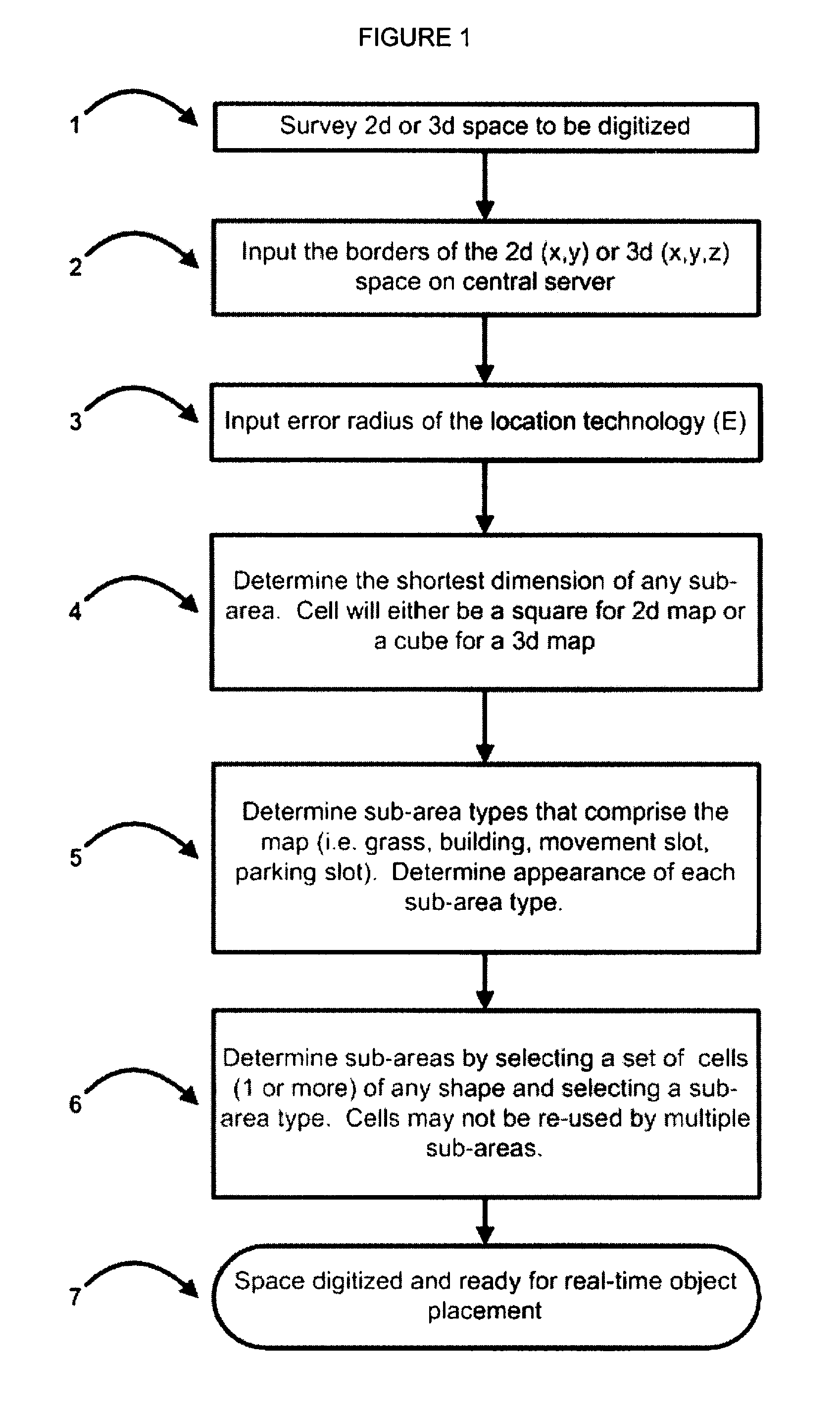
[0074]Firstly, as shown in FIG. 1, at step 1, the (2 or 3 dimensional) parking space to be digitized is surveyed. The borders of the space are then input on a central server at step 2. At step 3, the error radius E of the vehicle location technology is input. At step 4 the shortest dimension of any sub-area is input for determining minimum required individual cell size. (Cell will have square or cube shape for 2D or 3D map). At step 5, the various different physical types of the sub-areas are determined, (grass, building, movement slot, parking slot), together with the...


PUM


Abstract

A computer implemented method for displaying on a map a definitive image of precise locations of multiple mobile objects such as vehicles in a lot. The lot is mapped digitally to display precise locations of sub-areas of different types, such as parking and movement slots and their raw, approximate distances from vehicles are determined from approximate coordinates of vehicles obtained remotely. A data base of vehicle and sub-area types is established and a vehicle placement matrix is determined providing probabilities of respective sub-areas being occupiable by respective vehicles derived from business environment rules based on compatibilities of respective vehicle types with respect sub-area types. Raw, approximate distances of vehicles from sub-areas are divided by the probabilities to provided adjusted distances, sub-areas ranked by least adjusted distances and the respective vehicles placed in their top ranked sub-areas for more accurate display of location on a GUI.

Description

RELATED APPLICATION[0001]This is a continuation-in-part application of Ser. No. 12 / 028,262 filed Feb. 8, 2008 by Chowdhary and Chaudhry, the present applicants. The disclosure of the parent application is incorporated herein by reference.FIELD OF THE INVENTION[0002]The invention relates to tracking vehicle positions in a parking lot for definitive display on a GUI for the purposes of inventory management and inventory security.BACKGROUND OF INVENTION[0003]In the automotive and storage and distribution industries, effective inventory management applications are critical to daily operations, where locating vehicles, trailers, or other mobile inventory accurately and in a timely manner is critical to business success.[0004]At automotive dealerships, both sales and service employees routinely search for vehicles. If a salesperson cannot locate a vehicle for a prospective customer to test drive within a timely manner, the salesperson is less likely to sell a vehicle. On the service side,...

Claims


Application Information

Patent Timeline
Patent Type & Authority Applications(United States)
IPC IPC(8): G06F17/00
CPCG06F17/00G06Q10/087
Inventor CHOWDHARY, GAURAV
Owner CHOWDHARY GAURAV
Learn More