Trace component removal in co2 removal processes by means of a semipermeable membrane

a technology of semi-permeable membrane and trace component, which is applied in the direction of combustion process, combustion treatment, lighting and heating apparatus, etc., can solve the problems of high investment and operational costs

Active Publication Date: 2013-12-19
GENERAL ELECTRIC TECH GMBH
View PDF15 Cites 15 Cited by
  • Summary
  • Abstract
  • Description
  • Claims
  • Application Information

AI Technical Summary

Benefits of technology

[0008]It is an object of the present invention to reduce or prevent accumulation of trace components in the amm...

Problems solved by technology

The construction and operation of industrial gas purification systems, e.g. for the removal of CO2 from the...

Method used


Image

  • Trace component removal in co2 removal processes by means of a semipermeable membrane
  • Trace component removal in co2 removal processes by means of a semipermeable membrane
  • Trace component removal in co2 removal processes by means of a semipermeable membrane

Examples


Embodiment Construction

[0044]Herein, the invention will be described in detail with reference to the drawings.

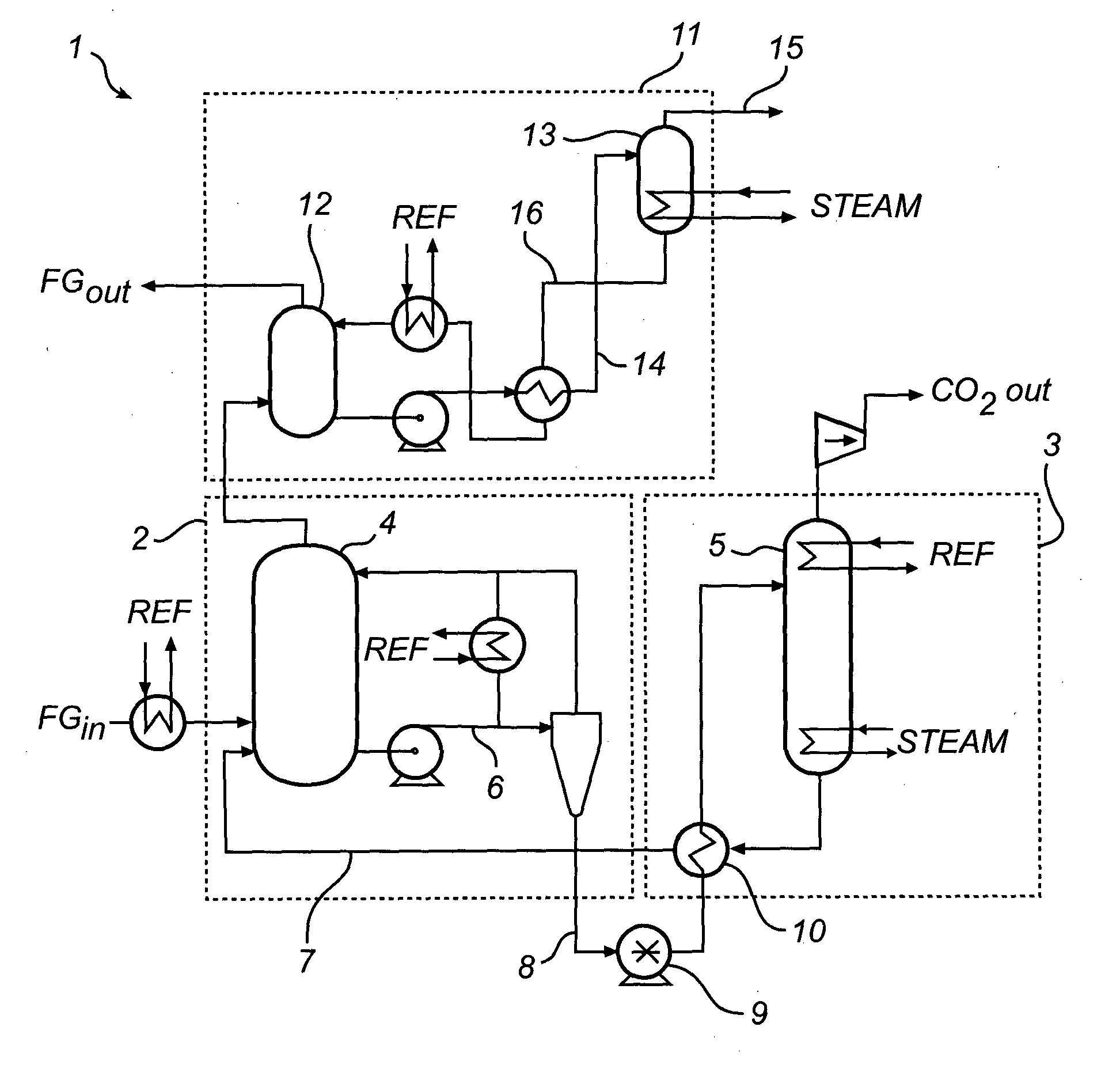
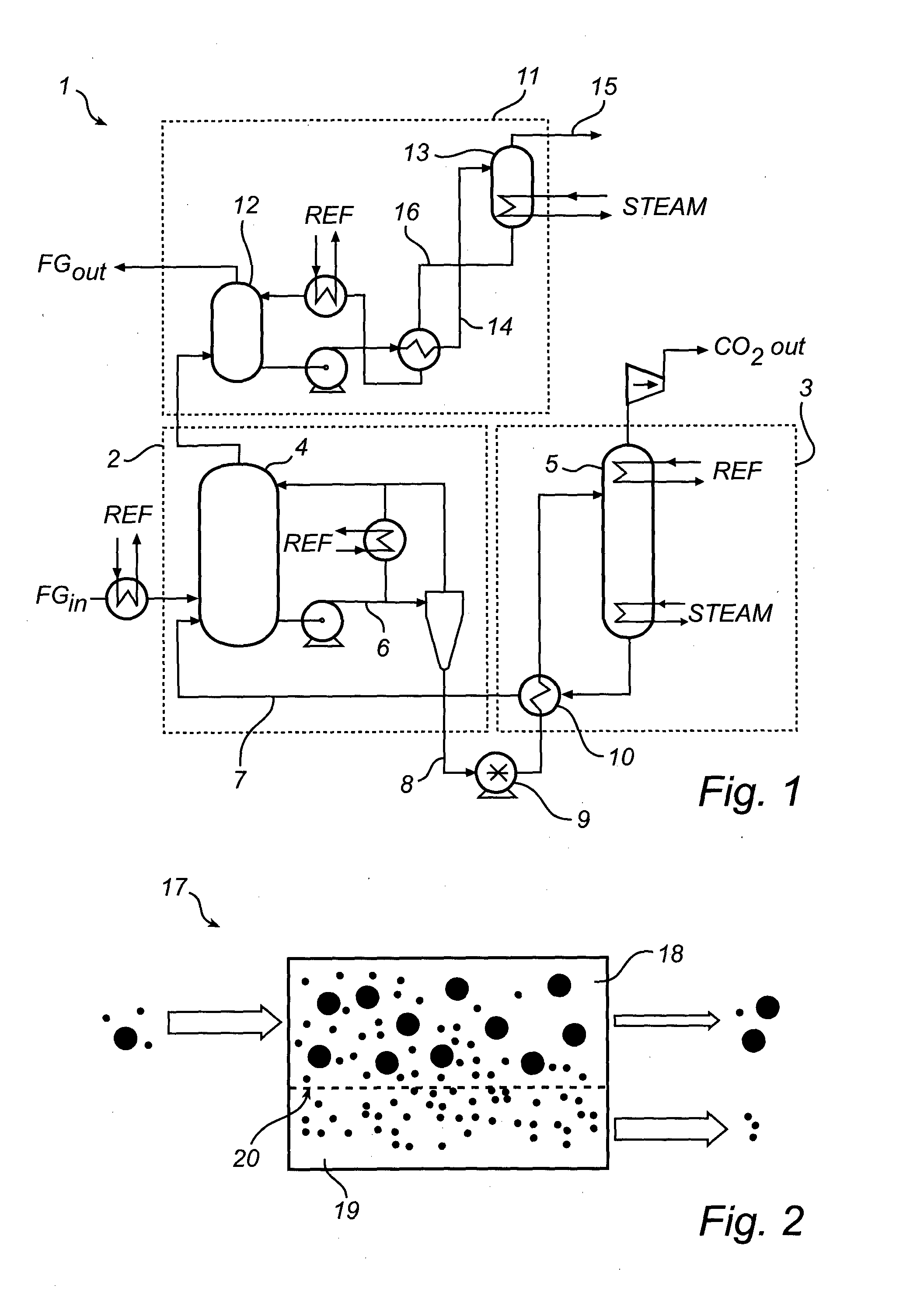
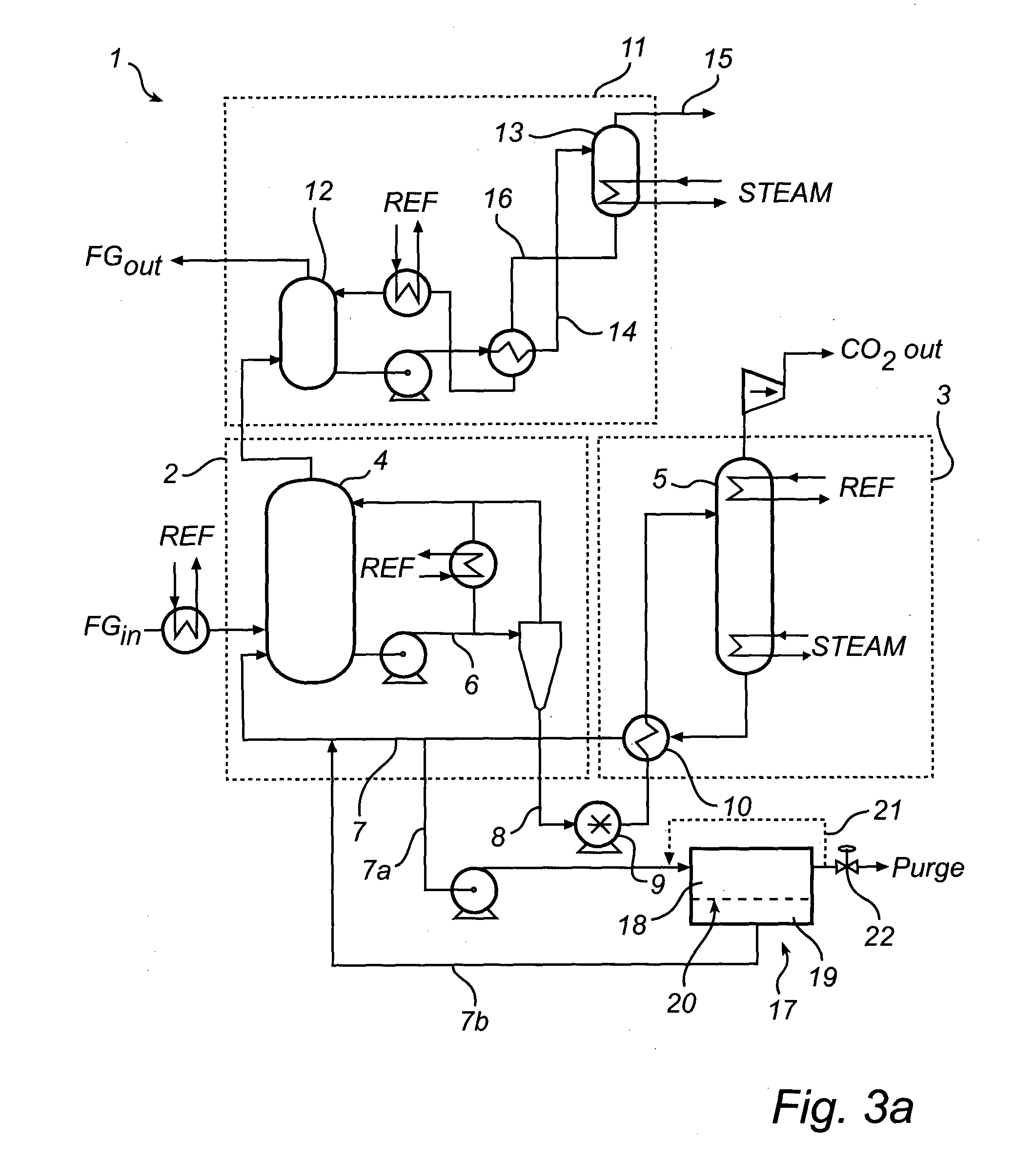
[0045]The CO2 removal system may generally form a part of a gas cleaning system for cleaning flue gas emitted by, e.g., the combustion chamber of a boiler system used in a steam generator system of a power generation plant. The gas cleaning system may comprise a dust removal system and a scrubber system configured for removal of particles and other contaminants from the flue gas. The CO2 removal system is configured to remove CO2 from the flue gas stream FG before emitting the cleaned flue gas stream to an exhaust stack (or alternatively additional processing). The CO2 removal system is also configured to output CO2 removed from the flue gas stream FG.

[0046]With reference to FIG. 1 the CO2 removal system 1 includes a capture section 2 for capturing and removing CO2 from a flue gas stream FG and a regeneration section 3 for regenerating ammoniated solution used to remove CO2 from the flue gas strea...


PUM

PropertyMeasurementUnit
Contentaaaaaaaaaa
Permeation propertiesaaaaaaaaaa

Abstract

A system (1) for removing carbon dioxide (CO2) from a gas stream by bringing the gas stream into contact with a circulating ammoniated solution stream such that CO2 is absorbed in said ammoniated solution, characterized in that the system comprises a membrane purifier (17), said membrane purifier having a first compartment (18) and a second compartment (19), wherein said first and second compartment are separated by a semipermeable membrane (20), a method for removing carbon dioxide (CO2) from a gas stream by bringing the gas stream into contact with a circulating ammoniated solution stream such that CO2 is absorbed in said ammoniated solution, said method comprising the step of separating trace components from a circulating solution using a semipermeable membrane, and the use of a membrane purifier having a first and a second compartment, wherein said first and a second compartments are separated by a semipermeable membrane, for reducing the trace component and/or water content of a circulating solution stream in a method or system for removing carbon dioxide (CO2) using a circulating ammoniated solution.

Description

FIELD OF THE INVENTION[0001]The proposed invention relates to a system and method for removing carbon dioxide (CO2) from a gas stream by bringing the gas stream into contact with a circulating ammoniated solution stream such that carbon dioxide is absorbed in said ammoniated solution. More particularly, the proposed invention is directed to a chilled ammonia based process and system for removing CO2 from a gas stream.BACKGROUND[0002]In the combustion of a fuel, such as coal, oil, peat, waste, etc., in a combustion plant, such as those associated with boiler systems for providing steam to a power plant, a hot process gas (or flue gas) is generated. Such a flue gas will often contain, among other things, carbon dioxide (CO2). The negative environmental effects of releasing carbon dioxide to the atmosphere have been widely recognized, and have resulted in the development of processes adapted for removing carbon dioxide from the hot process gas generated in the combustion of the above m...

Claims


Application Information

Patent Timeline
IPC IPC(8): B01D53/14
CPCB01D53/1425B01D53/1475B01D53/62B01D61/025B01D2252/102B01D2257/504B01D2258/0283F23J15/04F23J2215/50F23J2219/40Y02A50/20Y02C20/40Y02E20/32B01D53/14B01D61/00B01D53/96B01D53/229
Inventor BOCKMAN, JON K.KOCH, MICHAEL
Owner GENERAL ELECTRIC TECH GMBH
Why Eureka
Try Eureka