Trace component removal in CO2 removal processes by means of a semipermeable membrane

a technology of trace component and co2 removal, which is applied in the direction of combustion process, combustion treatment, chemical separation, etc., can solve the problems of high investment and operational costs

Active Publication Date: 2016-10-11
GENERAL ELECTRIC TECH GMBH
View PDF24 Cites 2 Cited by
  • Summary
  • Abstract
  • Description
  • Claims
  • Application Information

AI Technical Summary

Benefits of technology

[0009]It is an object of the present invention to reduce or prevent accumulation of trace components in the ammoniated solution of chilled ammonia based systems and processes for removal of carbon dioxide (CO2) from gas streams.
[0010]It is another object of the present invention to reduce or prevent accumulation of trace components in the ammoniated solution of chilled ammonia based systems and processes with no or low added energy requirement on the system.
[0011]The construction and operation of industrial gas purification systems, e.g. for the removal of CO2 from the flue gas produced by the boiler unit of a power plant, are associated with high investment and operational costs. The aspects described herein are based on the inventive realization that in a chilled ammonia process for removal of CO2 from a flue gas, significant process improvements and operational cost reduction can be achieved by the use of a membrane separation step. It has been found that a membrane separation step may advantageously be used instead of, or as a complement to, the conventionally used appendix stripper for the separation of trace components from water and lighter boilers.
[0016]The use of a membrane purifier as described herein has many advantages compared to bleed streams or appendix strippers previously used to control the amounts of trace components and / or water. For example, the energy requirement of the membrane purifier is very low and mainly related to pumping the feed stream to the purifier. Intermittent gaseous product streams, such as those produced by an appendix stripper, are avoided. Since no heating is required, no heat integration is necessary to make the operation economical. Independent operation without utility systems (steam, cooling etc.) is possible. In addition, the membrane purifier allows switching between different feed solutions such as, stripper bottoms, water wash bottoms and lean solution. Significantly less equipment and utility tie-ins are required for the membrane purifier compared to an appendix stripper. A membrane purifier has potential for a footprint reduction and lower investment costs. For example, one membrane for industrial application, with 7.6 m2 membrane area in a rolled module of about 1×0.1 m, would be able to purify about 300 l / hr. Due to the low operating temperatures (ambient temperature possible) the corrosion issues associated with higher temperatures, e.g. in strippers, are significantly reduced. In addition, undesired stripping of, e.g., sulfur compounds formed by sulfate decomposition is not possible.
[0037]According to other aspects illustrated herein, there is provided the use of a membrane purifier having a first and a second compartment, wherein said first and a second compartments are separated by a semipermeable membrane, for reducing the trace component and / or water content of a circulating solution stream in a method or system for removing carbon dioxide (CO2) using a circulating ammoniated solution.

Problems solved by technology

The construction and operation of industrial gas purification systems, e.g. for the removal of CO2 from the flue gas produced by the boiler unit of a power plant, are associated with high investment and operational costs.

Method used


Image

  • Trace component removal in CO2 removal processes by means of a semipermeable membrane
  • Trace component removal in CO2 removal processes by means of a semipermeable membrane
  • Trace component removal in CO2 removal processes by means of a semipermeable membrane

Examples


Embodiment Construction

[0045]Herein, the invention will be described in detail with reference to the drawings.

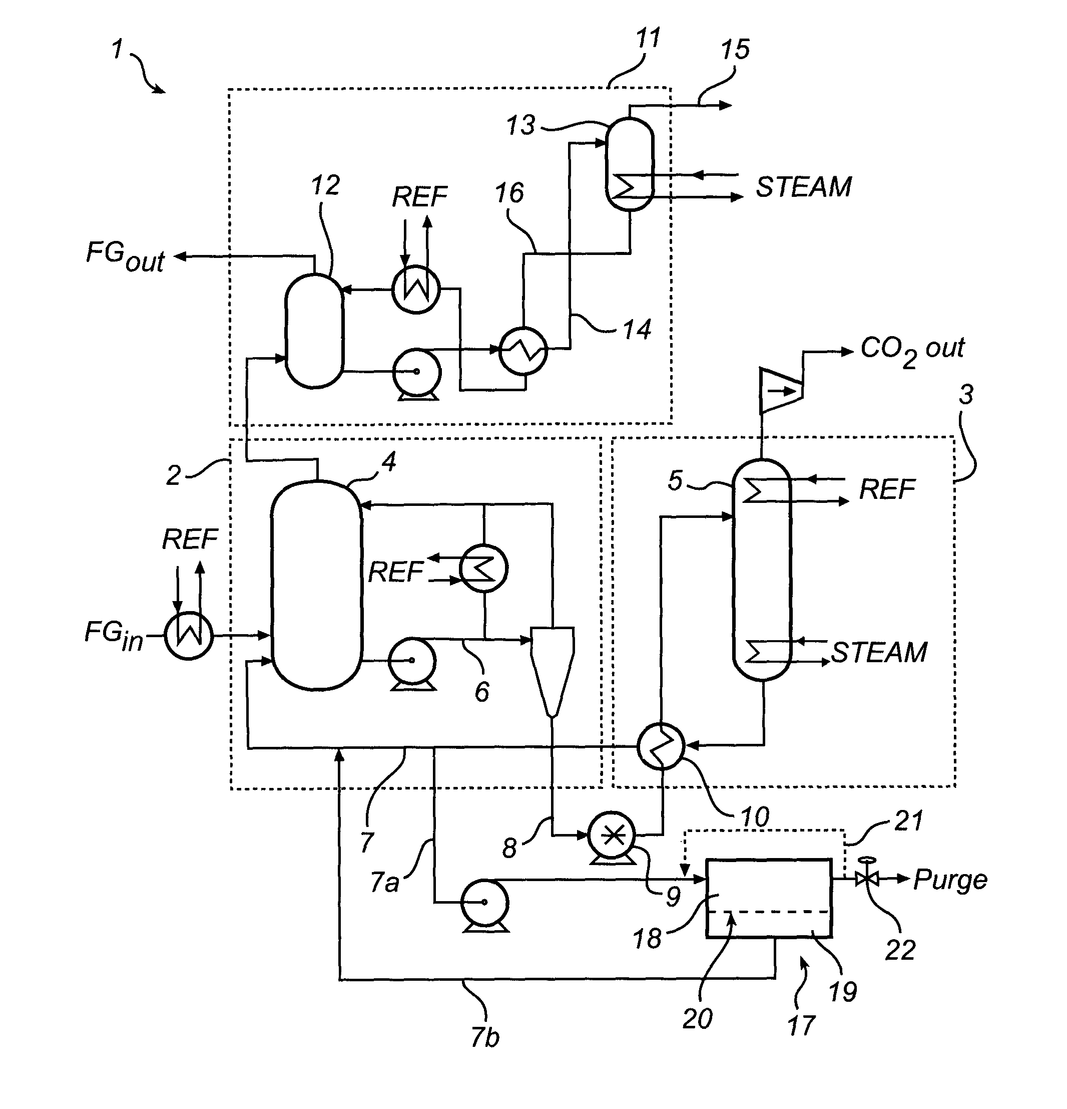
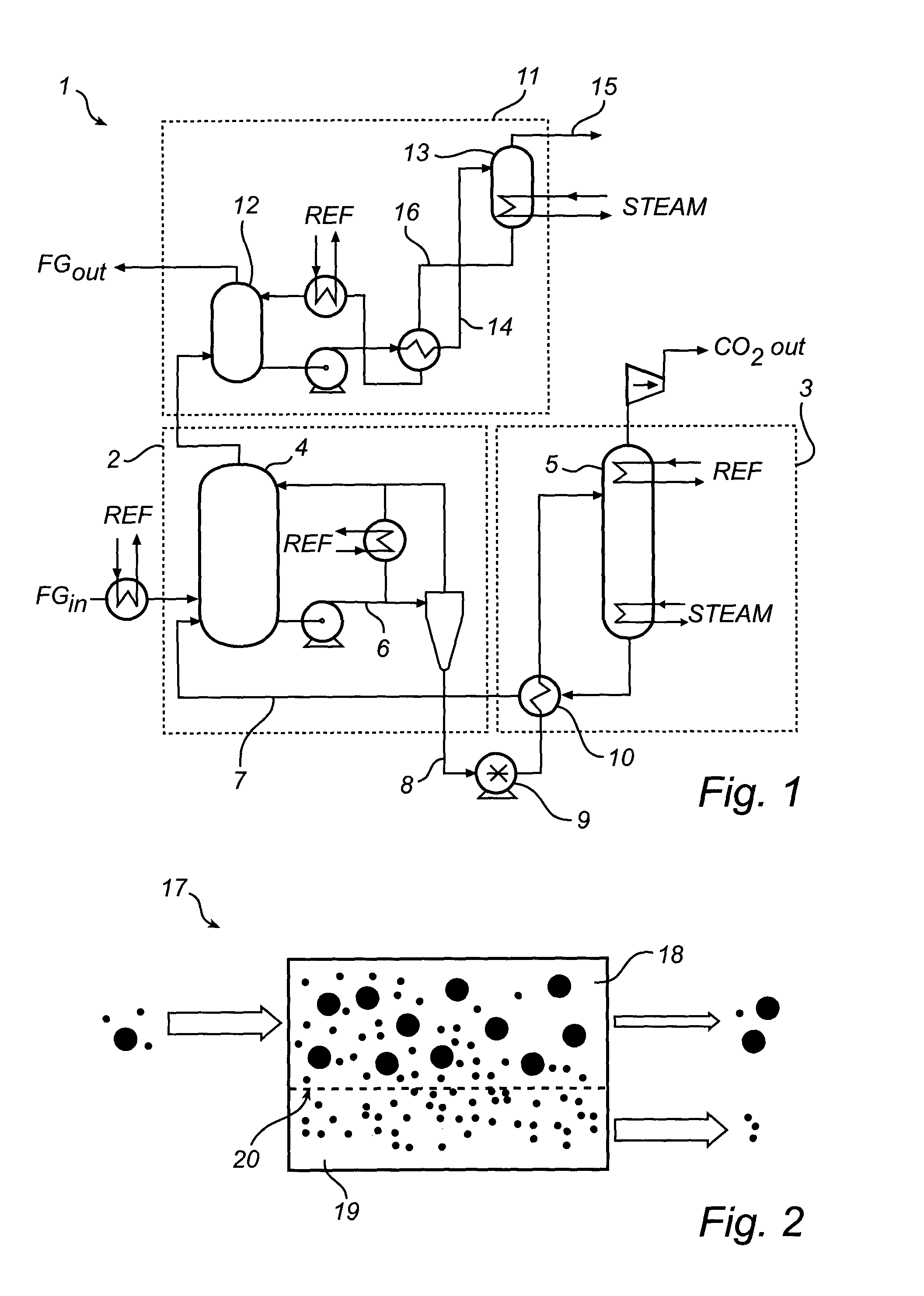
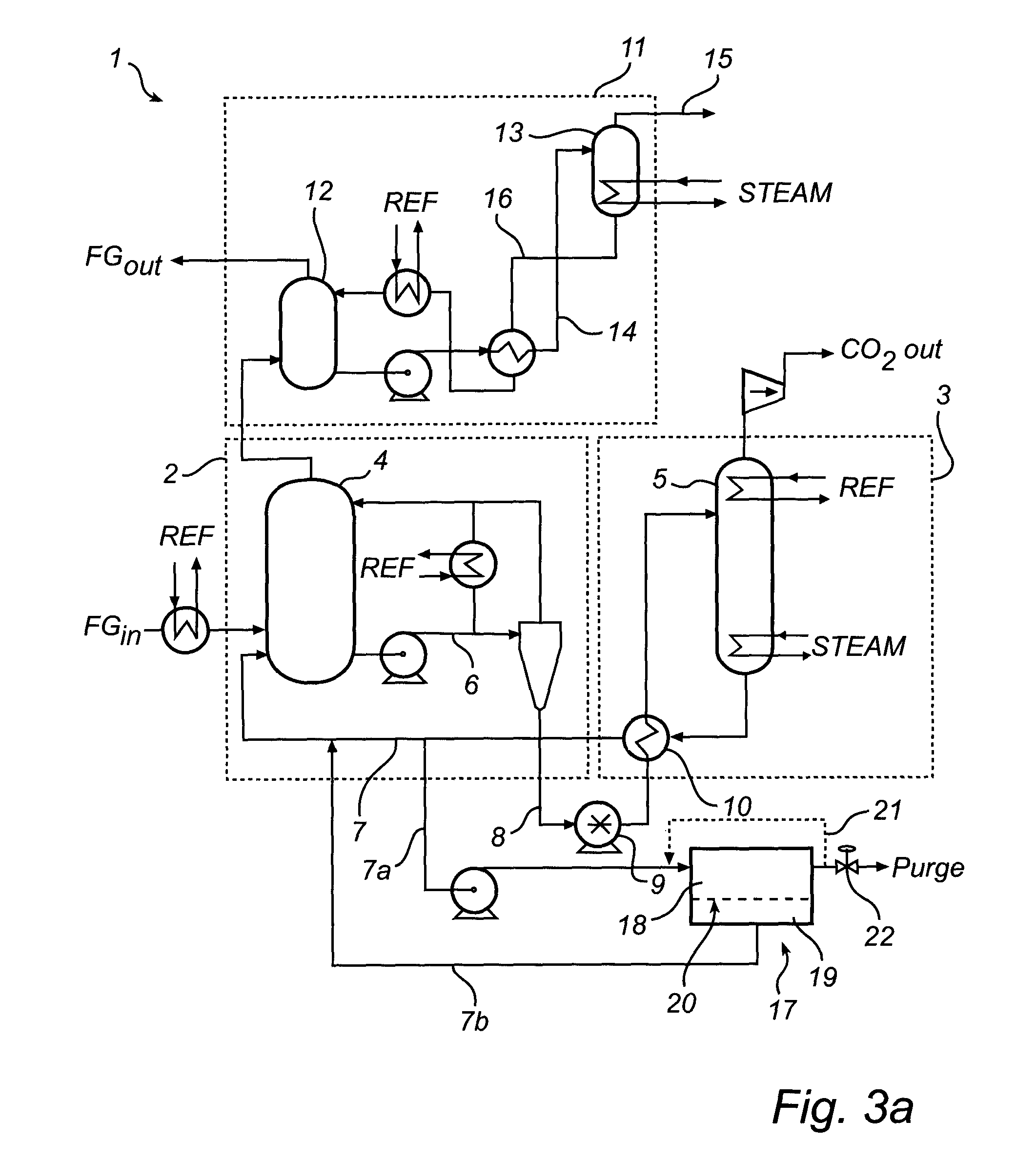
[0046]The CO2 removal system may generally form a part of a gas cleaning system for cleaning flue gas emitted by, e.g., the combustion chamber of a boiler system used in a steam generator system of a power generation plant. The gas cleaning system may comprise a dust removal system and a scrubber system configured for removal of particles and other contaminants from the flue gas. The CO2 removal system is configured to remove CO2 from the flue gas stream FG before emitting the cleaned flue gas stream to an exhaust stack (or alternatively additional processing). The CO2 removal system is also configured to output CO2 removed from the flue gas stream FG.

[0047]With reference to FIG. 1 the CO2 removal system 1 includes a capture section 2 for capturing and removing CO2 from a flue gas stream FG and a regeneration section 3 for regenerating ammoniated solution used to remove CO2 from the flue gas strea...


PUM

PropertyMeasurementUnit
temperatureaaaaaaaaaa

Abstract

A system (1) for removing carbon dioxide (CO2) from a gas stream by bringing the gas stream into contact with a circulating ammoniated solution stream such that CO2 is absorbed in said ammoniated solution, characterized in that the system comprises a membrane purifier (17), said membrane purifier having a first compartment (18) and a second compartment (19), wherein said first and second compartment are separated by a semipermeable membrane (20), a method for removing carbon dioxide (CO2) from a gas stream by bringing the gas stream into contact with a circulating ammoniated solution stream such that CO2 is absorbed in said ammoniated solution, said method comprising the step of separating trace components from a circulating solution using a semipermeable membrane, and the use of a membrane purifier having a first and a second compartment, wherein said first and a second compartments are separated by a semipermeable membrane, for reducing the trace component and / or water content of a circulating solution stream in a method or system for removing carbon dioxide (CO2) using a circulating ammoniated solution.

Description

[0001]This is a US National Phase application claiming priority to International Application No. PCT / IB2011 / 002136 having an International Filing Date of Sep. 14, 2011, incorporated herein in its entirety by reference.FIELD OF THE INVENTION[0002]The proposed invention relates to a system and method for removing carbon dioxide (CO2) from a gas stream by bringing the gas stream into contact with a circulating ammoniated solution stream such that carbon dioxide is absorbed in said ammoniated solution. More particularly, the proposed invention is directed to a chilled ammonia based process and system for removing CO2 from a gas stream.BACKGROUND[0003]In the combustion of a fuel, such as coal, oil, peat, waste, etc., in a combustion plant, such as those associated with boiler systems for providing steam to a power plant, a hot process gas (or flue gas) is generated. Such a flue gas will often contain, among other things, carbon dioxide (CO2). The negative environmental effects of releasi...

Claims


Application Information

Patent Timeline
Patent Type & Authority Patents(United States)
IPC IPC(8): B01D53/14B01D53/22B01D53/62F23J15/04B01D61/02
CPCB01D53/1425B01D53/1475B01D53/229B01D53/62B01D61/025F23J15/04B01D2252/102B01D2257/504B01D2258/0283F23J2215/50F23J2219/40Y02C10/04Y02C10/06Y02A50/20Y02C20/40Y02E20/32B01D53/14B01D61/00B01D53/96
Inventor BOCKMAN, JON KKOCH, MICHAEL
Owner GENERAL ELECTRIC TECH GMBH
Why Eureka
Try Eureka