Closed loop well twinning methods

a closed loop, wellbore technology, applied in the direction of borehole/well accessories, survey, construction, etc., can solve the problems of time-consuming drilling process, achieve the effect of improving the efficiency of drilling operation, reducing the total time required, and improving the placement accuracy of twin wells

Active Publication Date: 2013-12-19
PATHFINDER ENERGY SERVICES LLC +1
View PDF24 Cites 30 Cited by
  • Summary
  • Abstract
  • Description
  • Claims
  • Application Information

AI Technical Summary

Benefits of technology

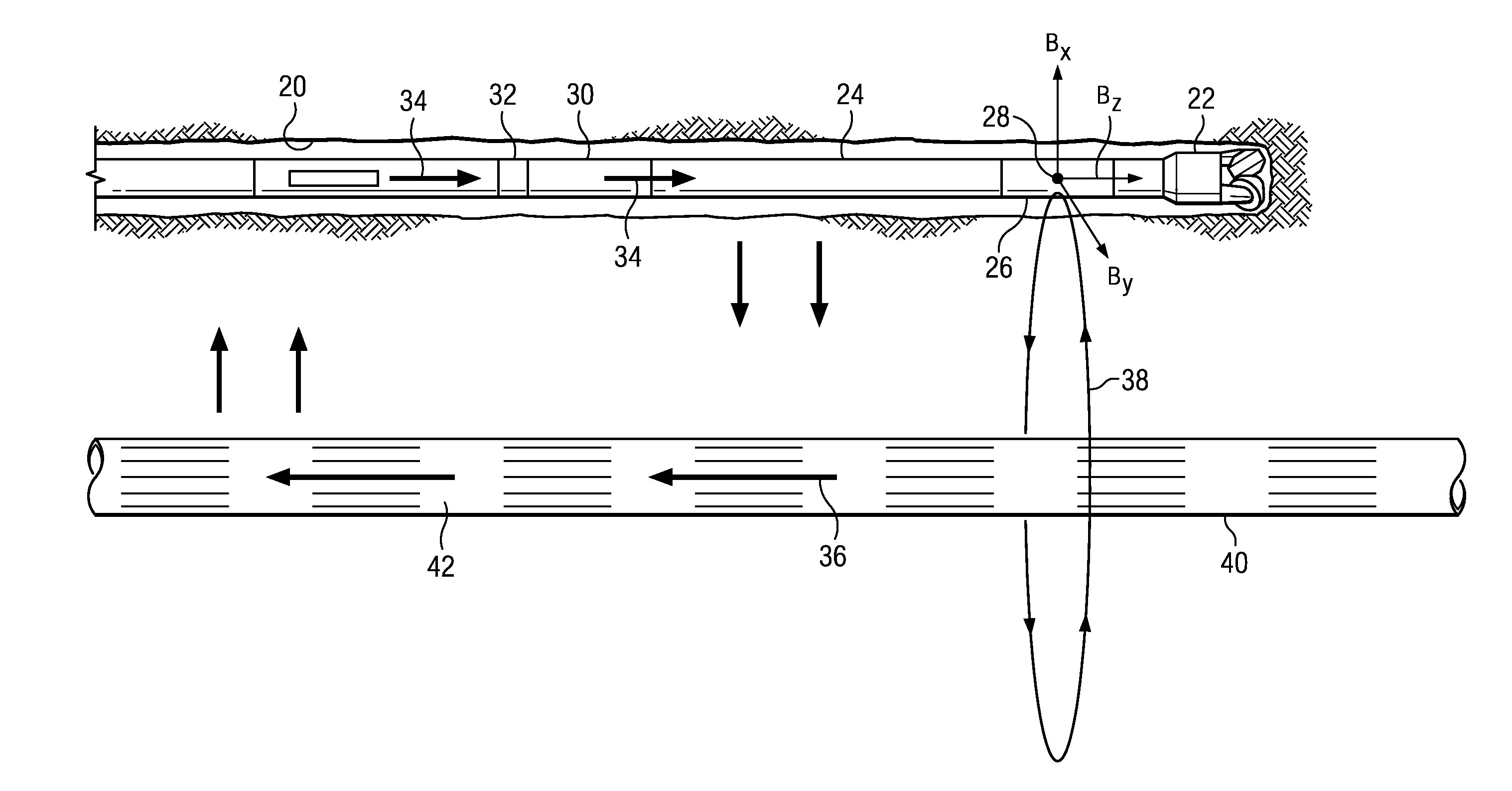
[0007]The disclosed embodiments may provide various technical advantages. For example, the disclosed methods may be used to steer the twin well automatically along a predetermined path with respect to the target well. No surface intervention is required. Such closed loop methods may therefore improve the efficiency of the drilling operation and significantly reduce the total time required to drill the twin well. The disclosed methods may further improve placement accuracy of the twin well with respect to the target well as the steering tool settings may be adjusted continually while drilling (e.g., at approximately 10 second intervals while drilling).

Problems solved by technology

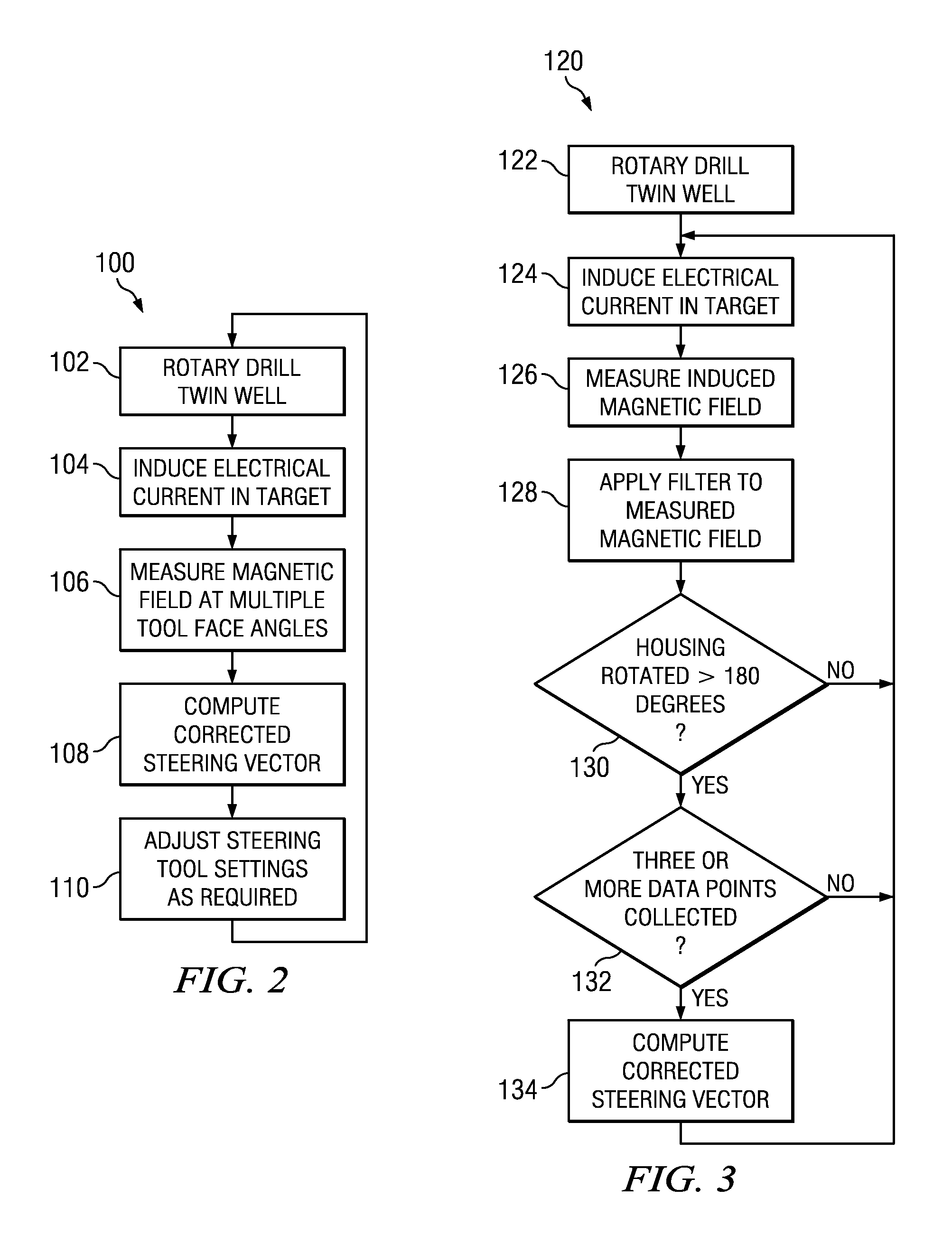
However, the need to stop drilling and make magnetic field measurements at three or more tool face angles can result in a time consuming drilling process.

Method used


Image

  • Closed loop well twinning methods
  • Closed loop well twinning methods
  • Closed loop well twinning methods

Examples


embodiment 150

[0038]FIG. 5A depicts a flowchart of yet another disclosed method embodiment 150. Method 150 is intended for use with a rotary steerable tool that rotates with the drill string. Method 150 may be used with a rotary steerable tool in which the magnetic field sensors are deployed in a housing that is rotationally coupled with the drill string or alternatively in a roll-stabilized housing. The magnetic field sensors may also be deployed in a separate MWD tool deployed above or below the rotary steerable tool in the BHA. When deployed in a roll-stabilized housing, sensors may be stationary with respect to the borehole or rotate relatively slowly with respect to the borehole (as compared to the rotation rate of the BHA). Method 150 is similar to method 120 in that the twin well is rotary drilled at 152 using a BHA including a rotary steerable tool. The rotary drilling operation may include circulating drilling fluid through the drill string, rotating the drill string at the surface, and ...

embodiment 180

[0041]FIG. 6A depicts a flowchart of still another disclosed method embodiment 180. Method 180 is intended for use with a rotary steerable tool in which the magnetic field sensors are deployed in a roll-stabilized housing. Being deployed in a roll-stabilized housing the magnetic field sensors may be non-rotating with respect to the borehole (e.g., in the bias phase) or may rotate slowly with respect to the borehole (e.g., in the neutral phase). The rotation rate in the neutral phase is much less than that of the BHA and other rotary steerable tool components (e.g., in a range from about 1 to about 5 revolutions per minute). For example, in one embodiment the BHA may rotate at 120 revolutions per minute (2 Hz) while the sensors may rotate at −3 revolutions per minute (i.e., in the opposite direction as the BHA). The disclosed embodiments are of course not limited to any particular rotation rates of the BHA and roll-stabilized housing.

[0042]Method 180 is similar to method 120 in that ...


PUM


Abstract

Closed loop methods for drilling twin wells are disclosed. The disclosed method make use of a bottom hole assembly including a rotary steerable tool. An electrical current is induced in the target well. The corresponding magnetic field about the target well is measured in the twin well and used to guide drilling of the twin well.

Description

CROSS REFERENCE TO RELATED APPLICATIONS[0001]None.FIELD OF THE INVENTION[0002]Disclosed embodiments relate generally to methods for drilling subterranean wellbores and more particularly to closed loop methods for twinning subterranean wellbores.BACKGROUND INFORMATION[0003]In various well drilling operations it is desirable to estimate the location of a nearby wellbore. Examples of such operations include well intercept, well avoidance, well twinning, and relief well drilling operations.[0004]Both passive and active magnetic ranging techniques are known in the oil field services industry. For example, U.S. Pat. Nos. 6,985,814 and 7,656,161 to McElhinney, disclose passive ranging methodologies for use in well twinning applications. The '814 patent makes use of remanent magnetization in a target well casing string while the '161 patent teaches a method for magnetizing the target well casing string prior to deployment in the target well.[0005]U.S. Pat. No. 7,812,610 to Clark teaches a m...

Claims


Application Information

Patent Timeline
Patent Type & Authority Applications(United States)
IPC IPC(8): E21B44/02E21B47/125
CPCE21B7/046E21B44/00E21B47/022
Inventor SUGIURA, JUNICHI
Owner PATHFINDER ENERGY SERVICES LLC
Why Eureka
Try Eureka