Resonating element, resonator, electronic device, electronic apparatus, and moving body

a resonator and resonator technology, applied in the direction of oscillator generators, piezoelectric/electrostrictive/magnetostrictive devices, piezoelectric/electrostriction/magnetostriction machines, etc., can solve the problem of inability to obtain desired frequency variable width, inability to achieve versatility of packages, and increase the capacitance ratio of quartz crystal resonators. achieve good frequency-temperature characteristics

Inactive Publication Date: 2013-12-19
SEIKO EPSON CORP
View PDF4 Cites 29 Cited by
  • Summary
  • Abstract
  • Description
  • Claims
  • Application Information

AI Technical Summary

Benefits of technology

[0039]According to this application example, there is an effect that a stable reference frequency source can be formed, and thus a moving body including a stable and accurate electronic control unit can be formed, using the resonating element with good frequency-temperature characteristics.

Problems solved by technology

Therefore, a capacitance of a package for the equivalent series capacitance C1 or a ratio of floating capacitances between electrodes increases, and, as a result, there is a problem in that the capacitance ratio γ of the quartz crystal resonator increases, and thereby a desired frequency variable width cannot be obtained.
However, in the piezoelectric resonator disclosed in JP-A-2-226905, a dedicated package in which the inductor circuit pattern is provided is necessary, and thus there is a problem in that a package does not have versatility.

Method used


Image

  • Resonating element, resonator, electronic device, electronic apparatus, and moving body
  • Resonating element, resonator, electronic device, electronic apparatus, and moving body
  • Resonating element, resonator, electronic device, electronic apparatus, and moving body

Examples


modification example 3

of Quartz Crystal Resonating Element

[0129]FIGS. 14A and 14B show a modification example of the quartz crystal resonating element, in which FIG. 14A is a schematic plan view when a structure of the quartz crystal resonating element according to the fourth embodiment of the invention is viewed from the top, and FIG. 14B is a cross-sectional view taken along the line J-J of FIG. 14A.

[0130]As shown in FIGS. 14A and 14B, a quartz crystal resonating element 303 according to the present modification example is formed by mounting the quartz crystal resonator element 1 on the intermediate substrate 302 which is a modification example of the intermediate substrate 2 of the embodiment shown in FIGS. 2A to 2C. The terminals 332a and 332b for joining to the quartz crystal resonator element 1 provided on one main surface of the intermediate substrate 302 are aligned with the corresponding external connection terminals 22a and 22b of the quartz crystal resonator element 1 and are joined thereto vi...

modification example 1

of Quartz Crystal Resonator Element

[0140]FIGS. 16A and 16B show a modification example of the quartz crystal resonator element, in which FIG. 16A is a schematic plan view when a structure of a quartz crystal resonator element according to a fifth embodiment of the invention is viewed from the top, and FIG. 16B is a cross-sectional view taken along the line L-L of FIG. 16A.

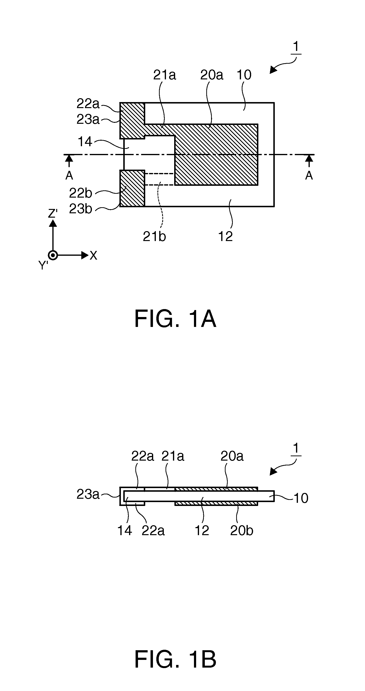
[0141]A quartz crystal resonator element 101 which is a modification example of the quartz crystal resonator element 1 of the embodiment shown in FIGS. 1A and 1B includes, as shown in FIG. 16A, a quartz crystal substrate 110, excitation electrodes 120a and 120b, and external connection terminals 122a and 122b. The quartz crystal substrate 110 includes a support portion 114 which is a fixed end and a vibrating portion 112 which is a free end. Here, the vibrating portion 112 according to the present modification example indicates a region which is interposed between mesa portions 116 formed on both main surfaces of t...

modification example 4

of Quartz Crystal Resonating Element

[0143]FIGS. 17A and 17B show a modification example of the quartz crystal resonating element, in which FIG. 17A is a schematic plan view when a structure of the quartz crystal resonating element according to the fifth embodiment of the invention is viewed from the top, and FIG. 17B is a cross-sectional view taken along the line M-M of FIG. 17A.

[0144]As shown in FIGS. 17A and 17B, a quartz crystal resonating element 304 according to the present modification example is formed by mounting a quartz crystal resonator element 101 which is a modification example of the quartz crystal resonator element 1 of the embodiment shown in FIGS. 1A and 1B on the intermediate substrate 2. The terminals 32a and 32b for joining to the quartz crystal resonator element 101 provided on one main surface of the intermediate substrate 2 are aligned with the corresponding external connection terminals 122a and 122b of the quartz crystal resonator element 101 and are joined ...


PUM


Abstract

A resonating element includes a resonator element that includes a vibrating portion and an excitation electrode provided on both main surfaces of the vibrating portion, an intermediate substrate in which the resonator element is mounted so as to be spaced from the excitation electrode, and a spiral electrode pattern that is provided on at least one main surface of the intermediate substrate, in which the electrode pattern is electrically connected to the excitation electrode.

Description

BACKGROUND[0001]1. Technical Field[0002]The present invention relates to a resonating element, a resonator, an electronic device, an electronic apparatus, and a moving body.[0003]2. Related Art[0004]In the related art, a surface mounting type electronic device has been widely used in which a piezoelectric resonator element where an excitation electrode is formed on a piezoelectric substrate is air-tightly sealed in a package. Here, the piezoelectric resonator element uses an AT cut quartz crystal resonator element or the like which performs thickness-shear vibration and employs, for example, a thin plate into which a piezoelectric substrate is cut at a cut angle called an AT cut, by using the characteristics in which the thin plate into which the piezoelectric substrate such as a quartz crystal is cut at a predetermined angle and thickness has an inherent resonance frequency.[0005]For example, a surface mounting type quartz crystal oscillator, in which a quartz crystal resonator ele...

Claims


Application Information

Patent Timeline
Patent Type & Authority Applications(United States)
IPC IPC(8): H01L41/047H03B5/32
CPCH01L41/0475H03B5/32H03H9/0547H03H9/1021H03B5/368H10N30/875
Inventor ISHII, OSAMUNOMURA, MASATAKA
Owner SEIKO EPSON CORP
Why Eureka
Try Eureka