Image processing device and method

a processing device and image technology, applied in the field of image processing devices and methods, can solve problems such as affecting image quality, and achieve the effects of reducing noise, enhancing local contrast, and suitably reducing nois

Inactive Publication Date: 2013-12-19
MITSUBISHI ELECTRIC CORP
View PDF14 Cites 4 Cited by
  • Summary
  • Abstract
  • Description
  • Claims
  • Application Information

AI Technical Summary

Benefits of technology

[0028]According to the present invention, a noise reduction coefficient for reducing noise can be set according to a coefficient for enhancing local contrast, so that noise can be suitably reduced according to the degree to which noise is amplified during local contrast enhancement.
[0029]Since the present invention also provides a 3-D noise reduction means for smoothing noise components over a plurality of frames of an image in the time direction, it can reduce random noise components alone without attenuating the amplitude of an enhanced subject signal. Furthermore, noise can be reduced without causing edge blur in still images.
[0030]Accordingly, the contrast of parts with reduced contrast in a low-contrast image captured under poor weather conditions such as fog or haze can be suitably enhanced, and the noise that is also enhanced when the contrast is enhanced can be reduced, whereby a high definition image can be obtained.

Problems solved by technology

A problem with stretching the range of the luminance distribution, however, has been that it amplifies not only the signal but also noise in the stretched luminance levels, impairing the quality of the image.

Method used


Image

  • Image processing device and method
  • Image processing device and method
  • Image processing device and method

Examples


first embodiment

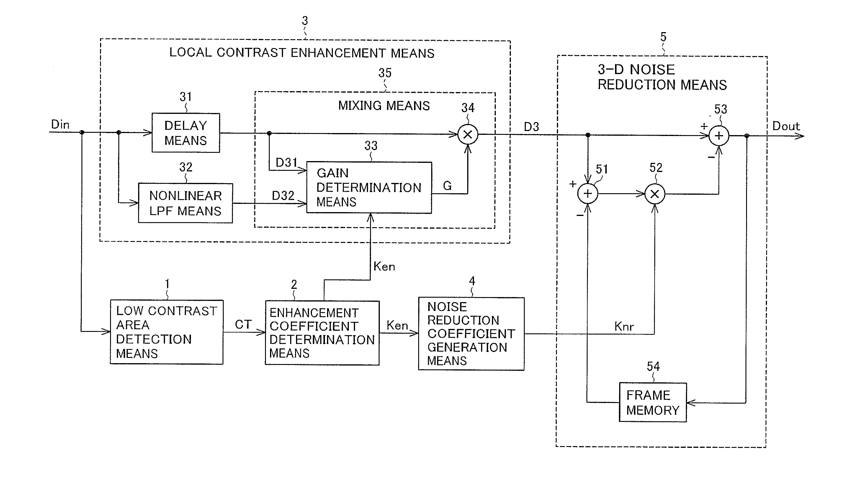
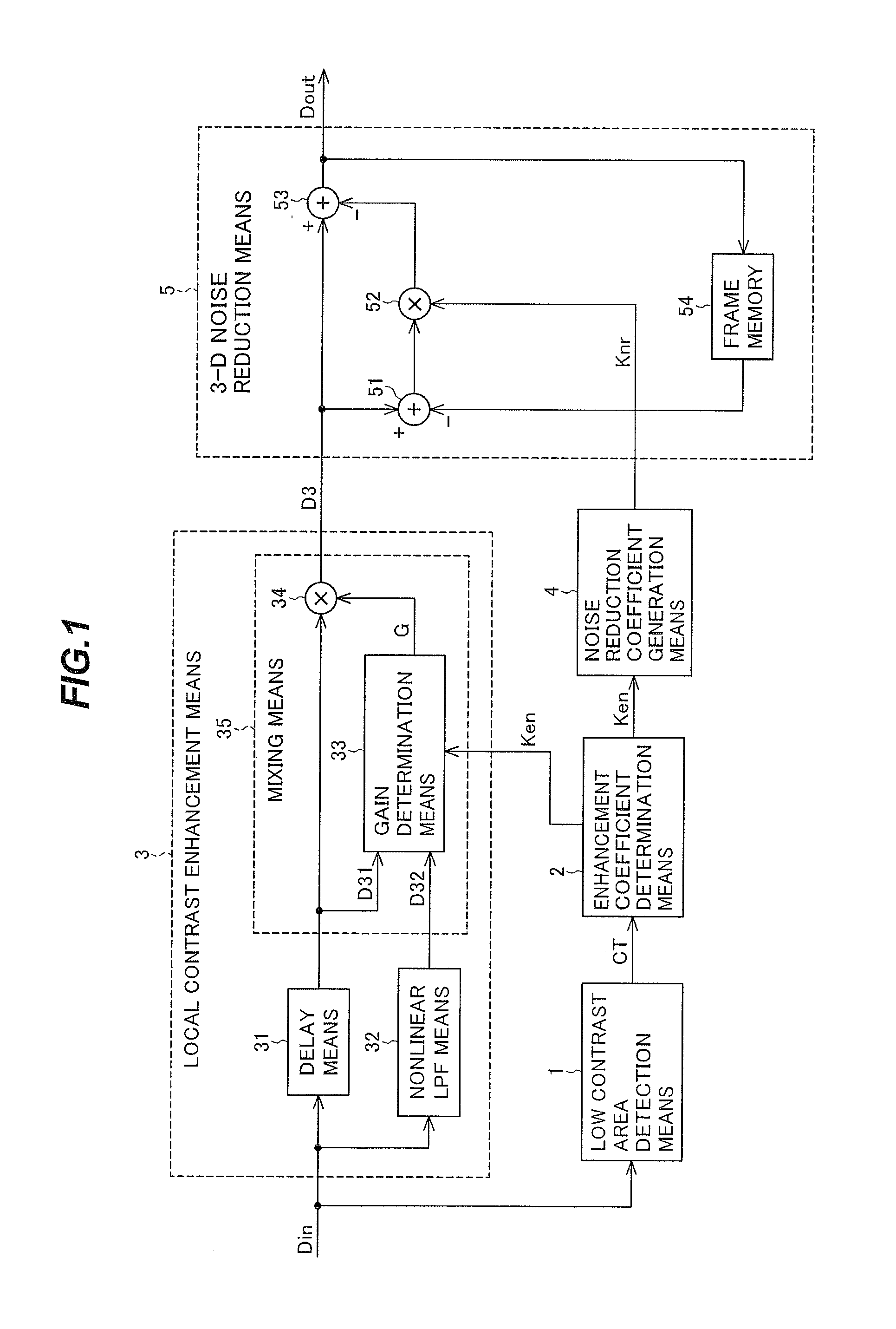
[0043]FIG. 1 is a block diagram showing the configuration of the image processing device according to the first embodiment of the invention. The image processing device according to the first embodiment includes a low contrast area detection means 1, an enhancement coefficient determination means 2, a noise reduction coefficient generation means 4, and a 3-D noise reduction means 5.

[0044]The low contrast area detection means 1 receives an input image signal representing an input image Din and, for each pixel in the input image Din, detects a contrast correlation value CT of a surrounding area centered on the pixel to be corrected. The input image and the input image signal representing it will be denoted by the same symbol Din. Other signals will be similarly denoted below.

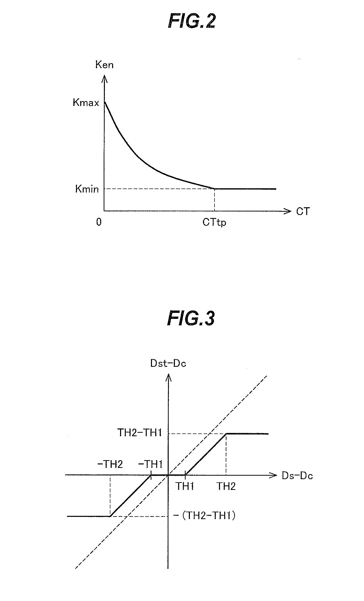
[0045]The enhancement coefficient determination means 2 determines a contrast enhancement coefficient Ken for each pixel according to the contrast correlation value CT detected by the low contrast area detection m...

second embodiment

[0125]FIG. 8 is a block diagram showing the configuration of the image processing device according to the second embodiment of the invention. Differing from the first embodiment, the image processing device according to the second embodiment has a configuration in which the 3-D noise reduction means is located in a stage preceding the low contrast area detection means and local contrast enhancement means.

[0126]The image processing device according to the second embodiment includes a 3-D noise reduction means 105, a low contrast area detection means 101, an enhancement coefficient determination means 102, a local contrast enhancement means 103, a noise reduction coefficient generation means 104, and a frame memory 106.

[0127]The 3-D noise reduction means 105 has the same configuration as the 3-D noise reduction means 5 in the first embodiment, but receives the input image Din instead of the intermediate image D3 as its input, and smoothes noise components in the time direction over a ...

third embodiment

[0151]FIG. 11 is a block diagram showing the configuration of the image processing device according to the third embodiment of the invention. Differing from the first embodiment, the image processing device according the third embodiment performs detection of low contrast parts and determination of the enhancement coefficient Ken, gain G, and noise reduction coefficient Knr on the basis of a luminance signal Yin (a first image signal) representing a luminance component of the image, and performs local contrast enhancement with the determined gain G and noise reduction with the determined noise reduction coefficient Knr on the color image signal Rin, Gih, Bin (a second image signal) of each of the red (R), green (G), and blue (B) color components in the same image.

[0152]The image processing device in FIG. 11 includes a low contrast area detection means 201, an enhancement coefficient determination means 202, a local contrast enhancement means 203, a noise reduction coefficient genera...


PUM


Abstract

For each pixel in an image (Din), a contrast correlation value (CT) is detected for peripheral areas centered around the pixel to be corrected (1), a contrast enhancement coefficient (Ken) is determined in accordance with the contrast correlation value (CT) (2), and in accordance with the enhancement coefficient (Ken), local contrast is enhanced for each pixel and an intermediate image (D3) is generated (3). When performing noise reduction (5) by smoothing the intermediate image (D3) in the time direction, the degree of noise reduction is controlled in accordance with a noise reduction coefficient (Knr) that is large where the enhancement coefficient (Ken) is large. With respect to a low-contrast image such as one captured under fog, haze or other poor weather conditions, the contrast in areas having reduced contrast is appropriately improved, and the noise that is enhanced in conjunction with contrast improvement is reduced, enabling a high quality image to be obtained.

Description

TECHNICAL FIELD[0001]The present invention relates to an image processing device and method that correct the contrast of an image, more particularly to a process that improves image contrast and sharpness to increase the visibility of a low-contrast image captured under bad weather conditions such as fog or haze, and reduce the enhanced noise produced thereby.BACKGROUND ART[0002]Various contrast enhancement methods have been proposed as techniques for generating a sharp image by correcting a low-contrast image.[0003]The gradation correction device described in Patent Document 1, for example, generates a luminance signal from primary color signals, detects information about the distribution of the generated luminance signal over the entire screen, creates a gradation correction conversion table for smoothing the histogram distribution over the entire range of luminance levels, calculates correction coefficients based on the input / output ratio of the gradation correction conversion ta...

Claims


Application Information

Patent Timeline
Patent Type & Authority Applications(United States)
IPC IPC(8): G06T5/20
CPCG06T5/20H04N5/21G06T5/002G06T5/008G06T2207/20182
Inventor TOYODA, YOSHITAKASUZUKI, DAISUKEYAMASHITA, KOICHIITO, TAKASHIMATOBA, NARIHIRO
Owner MITSUBISHI ELECTRIC CORP
Why Eureka
Try Eureka