
Deep tissue focal fluorescence imaging with digitally time-reversed ultrasound-encoded light

a fluorescence imaging and deep tissue technology, applied in the field of imaging and scattering media irradiation, can solve the problem of severe impeded imaging of thick biological samples beyond the ballistic regim

Active Publication Date: 2013-12-26
LONDON SCHOOL OF HYGIENE & TROPICAL MEDICINE +1
View PDF4 Cites 15 Cited by
  • Summary
  • Abstract
  • Description
  • Claims
  • Application Information

AI Technical Summary

Benefits of technology

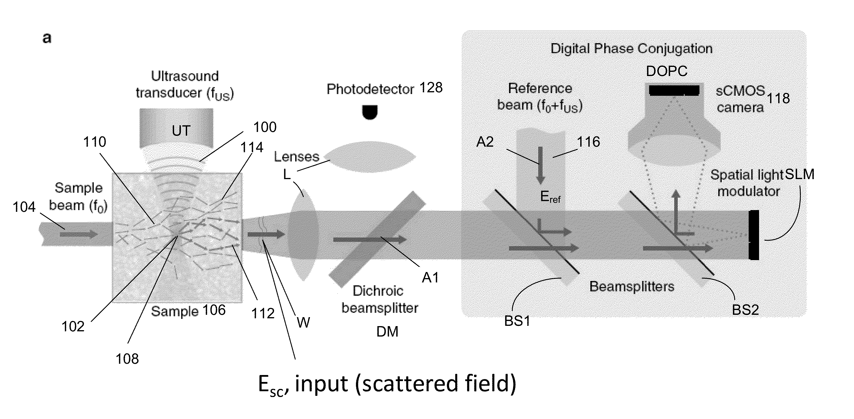
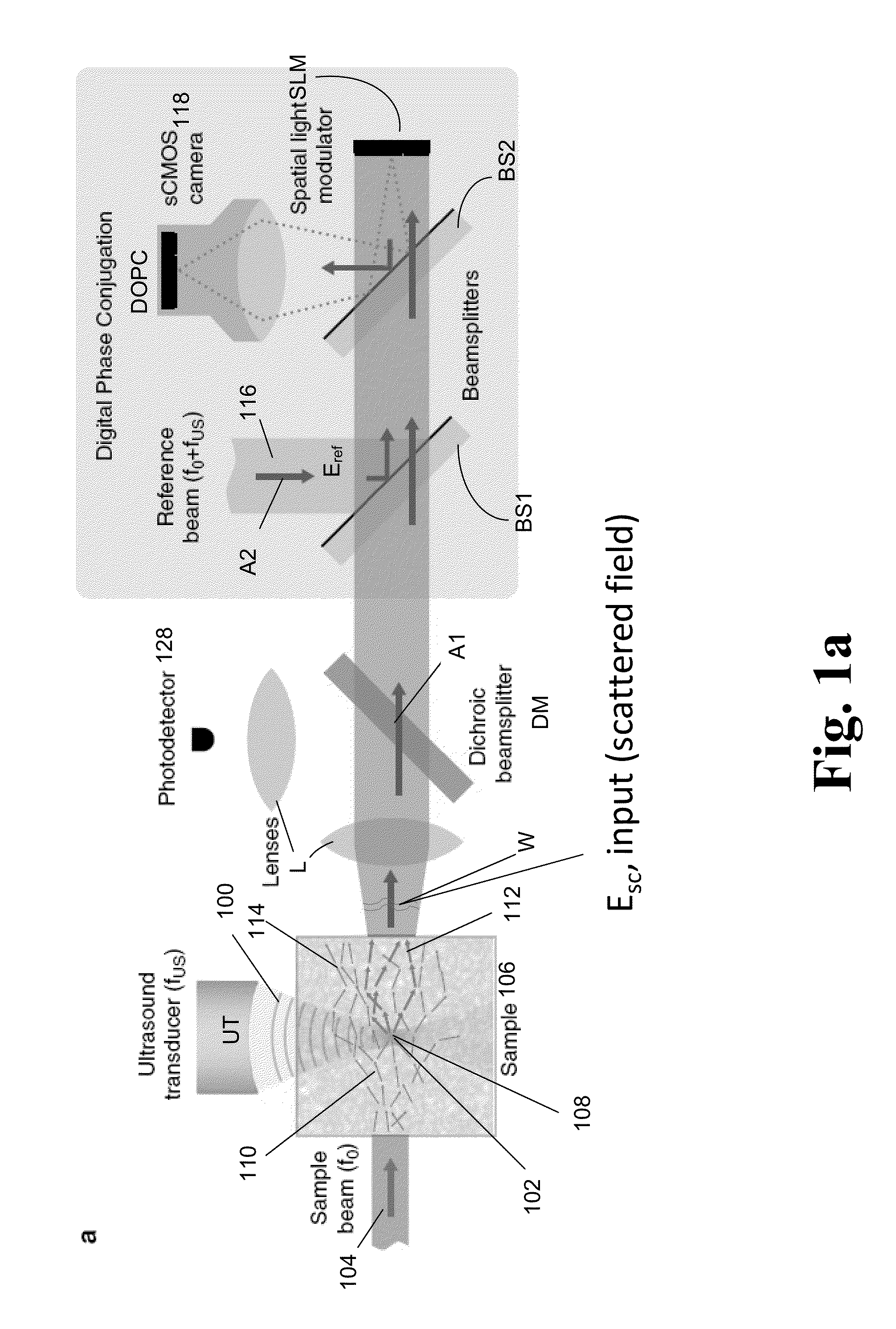
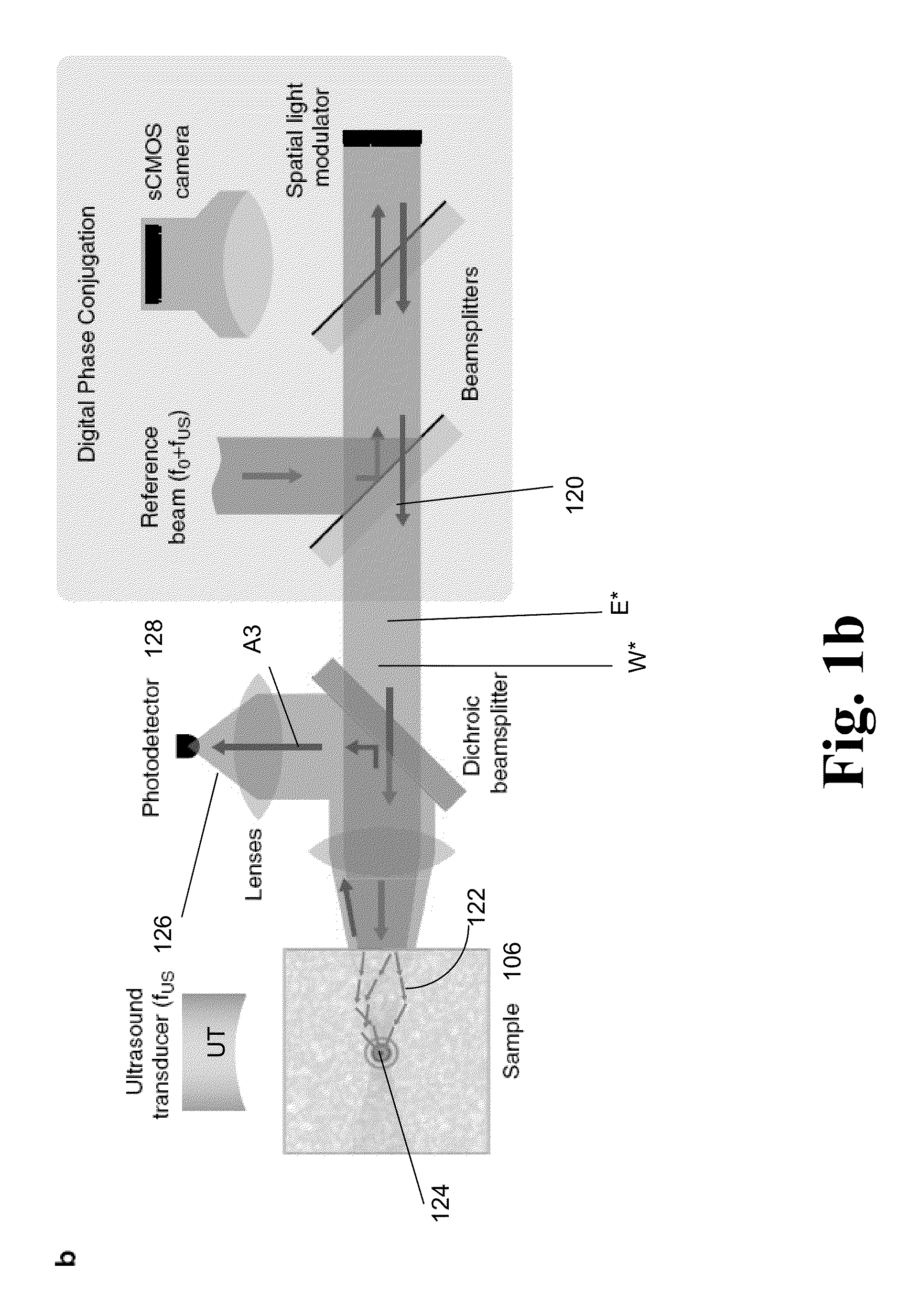
The patent describes a method for improving fluorescence imaging in biomedical science by using ultrasound to focus light inside biological tissues. The method involves using a spatial light modulator to create a time reversed field that is phase conjugated to the light, which is then irradiated onto the tissue. The resulting fluorescence is detected using a detector and a computer. The method can be used to image complex fluorescent objects and tumor microtissues at a depth of 2.5 mm in biological tissues. The technical effect of the method is the ability to image deep inside biological samples with high resolution and high optical gain.

Problems solved by technology

However, scattering of light severely impedes imaging of thick biological samples beyond the ballistic regime.

Method used


Image

  • Deep tissue focal fluorescence imaging with digitally time-reversed ultrasound-encoded light
  • Deep tissue focal fluorescence imaging with digitally time-reversed ultrasound-encoded light
  • Deep tissue focal fluorescence imaging with digitally time-reversed ultrasound-encoded light

Examples


case 1

[0140] Phase and Amplitude Time-Reversal

[0141]Assuming the phase conjugate mirror has unit reflectivity and invoking the time-symmetric property of the transmission matrix, the phase conjugate, Ê1Ais

?=∑nN?(?)=(?)∑nN?2?indicates text missing or illegible when filedEq7

[0142]and its intensity is

?=[?∑nN?2]2=?[∑nN?2]2=?α2?indicates text missing or illegible when filedEq8

[0143]Thus, we find that the input speckle considered is reconstructed with some pre-factor, α2=[ΣnN|t1nAB|2]2, determined by the transmission properties of the turbid medium. In a random scattering medium, the ensemble average of α2 can be found by considering the statistics of the circular Gaussian distribution and in so recognizing that α itself follows the Gamma distribution, (N,2σ2). We thus obtain

(α2)=4N(N+1σ  Eq 9

[0144]We will now show that the elements at plane A with zero input will have non-zero phase conjugate intensities (i.e., ÎmA>0 for m≠1), constituting a phase conjugate background. We let the transmission ...

case 2

[0149] Phase Only Time-Reversal

[0150]In the case where a phase only phase conjugate mirror is used, the phase conjugated electric field and intensity of the input speckle, respectively, are

?=(?)∑nN??[-?Arg(?)]=∑nN?Eq14?=?[∑nN?]2?indicates text missing or illegible when filedEq15

[0151]and the derivations of PBRphase only follows exactly that of Vellekoop et. al. for the case of iterative wavefront optimization to multiple targets through scattering medium38, obtaining for N>>1:

PBRphaseonly=π4(N-1)+1M≈π4·PBRphase&amplitudeEq16

[0152]3. Phase Jitter in Acoustic Wave

[0153]The technique illustrated in FIG. 1c relies on the detection of 45 MHz ultrasound frequency-shifted light in the presence of a large background of non-shifted light. While the reference beam (equally frequency shifted by 45 MHz) interferes with US-tagged light, interference of the reference beam with the non-shifted light occurs at a beating frequency of 45 MHz (cycle time: 22.2 ns). This beating usually averages ou...


PUM


Abstract

A device and method for performing fluorescence imaging with digitally time reversed ultrasound encoded light, using a source of ultrasound waves, a coherent light source, a digital optical phase conjugation (DOPC) device comprising a camera and a spatial light modulator (SLM), a detector of fluorescence, and one or more computers, to obtain an output that at least approximates an interaction between a complete time reversed field, of all of the encoded light's fields, and the scattering medium.

Description

CROSS REFERENCE TO RELATED APPLICATIONS[0001]This application claims priority under 35 U.S.C. §119(e) to the following co-pending and commonly-assigned U.S. patent application:[0002]U.S. Provisional Patent Application Ser. No. 61 / 616,347, filed on Mar. 27, 2012, by Ying Min Wang, Benjamin Judkewitz, Charles A. DiMarzio, and Changhuei Yang, entitled “DEEP TISSUE FLUORESCENCE IMAGING USING DIGITALLY TIME-REVERSED ULTRASOUND-ENCODED LIGHT,” attorneys' docket number 176.81-US-P1 (CIT-6150-P), which application is incorporated by reference herein.[0003]This application is related to the following co-pending and commonly-assigned patent applications, which applications are incorporated by reference herein:[0004]U.S. Utility patent application Ser. No. 12 / 886,320, filed on Sep. 20, 2010, by Zahid Yaqoob, Emily McDowell and Changhuei Yang, entitled “OPTICAL PHASE PROCESSING IN A SCATTERING MEDIUM,” attorney's docket number 176.54-US-D1, which application is a divisional of U.S. Utility pate...

Claims


Application Information

Patent Timeline
Patent Type & Authority Applications(United States)
IPC IPC(8): H04N5/30
CPCH04N5/30A61N5/00G01N27/44721G02F1/11
Inventor WANG, YING MINJUDKEWITZ, BENJAMINDIMARZIO, CHARLES A.YANG, CHANGHUEI
Owner LONDON SCHOOL OF HYGIENE & TROPICAL MEDICINE
Learn More