
Technique for Enhancing the Quality of Compressed Video Images

a video image and compression technology, applied in the field of optical systems, can solve the problems of low quality video not being useful as evidence, creating additional burden and cost for network operators, and problems such as the storage of all the data generated by high-definition security cameras, and achieves the effect of reducing noise artifacts and great compression

Inactive Publication Date: 2013-12-26
CABLE TELEVISION LAB
View PDF10 Cites 24 Cited by
  • Summary
  • Abstract
  • Description
  • Claims
  • Application Information

AI Technical Summary

Benefits of technology

The patent is about a way to make videos from images that have been taken using a camera, or from a stream of data that has been recorded. A processor makes changes to the images to make them look better and reduce noise. This helps to make the video look better and easier to watch.

Problems solved by technology

Low quality video is not useful as evidence and allows criminals to escape justice and commit more crimes.
Another problem is the huge quantities of security camera data that are transported onto the Internet, which creates additional burden and cost for network operators such as Multiple System Operators, including cable companies.
Storage systems also have problems storing all of the data generated by high-definition security cameras.
Storing large quantities of video data, typically on Flash memory or hard drives, is costly.
Another problem is that infrared light emitting diodes (LEDs) are frequently used to illuminate a security camera's field of view at night, but the pictures at a distance are typically grainy.

Method used


Image

  • Technique for Enhancing the Quality of Compressed Video Images
  • Technique for Enhancing the Quality of Compressed Video Images
  • Technique for Enhancing the Quality of Compressed Video Images

Examples


Embodiment Construction

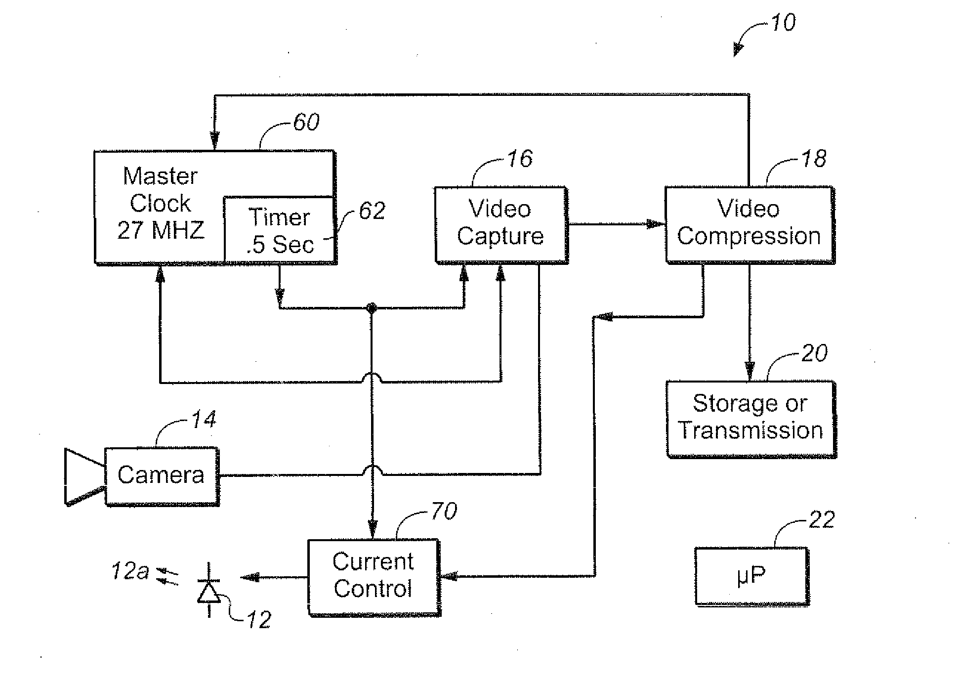
[0013]FIG. 1 is a block diagram of an imaging system 10 to illustrate an embodiment of the invention. A light source 12, comprising for example one or more light emitting diodes (LEDs), (even though only one LED shown in FIG. 1), generates light along arrows 12a to illuminate a scene (not shown). Light from the scene is sensed by a camera 14, which provides images of the scene to an imaging capture device such as video capture block 16. Camera 14 may be any conventional type, such as one employing CCD or CMOS devices that accumulate electrical charges in response to light. Video capture block 16 converts analog or digital signals from the camera 12 into a digital stream which is supplied to video compression block 18 where the digitized images are compressed using a conventional technique, such as one according to one of the MPEG standards. The compressed images are then transmitted to a communication network such as a cable network or the internet 20 or are stored in a storage medi...


PUM


Abstract

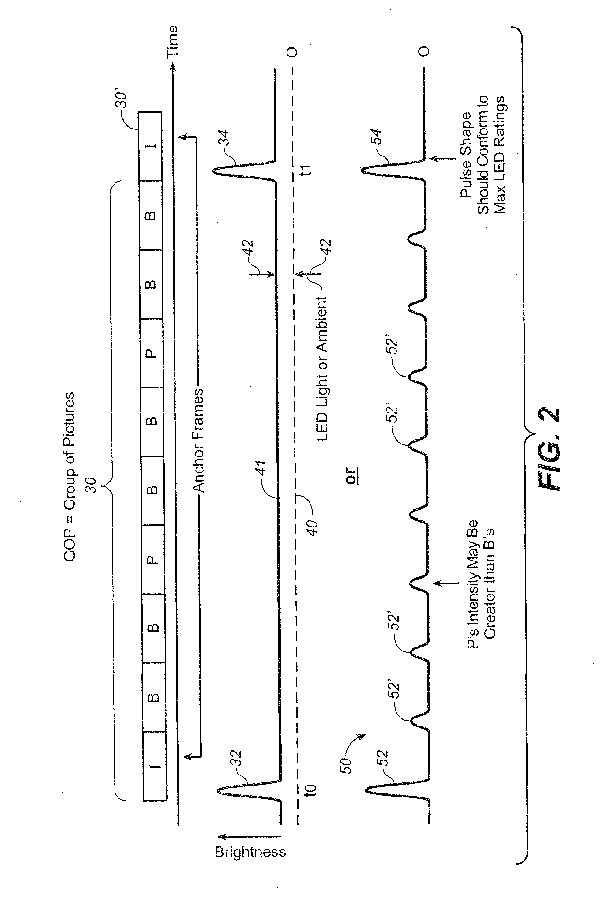
The scene is illuminated by light pulses at higher intensities at predetermined times than at times between the predetermined times. Images of the scene are captured at the predetermined times to provide a sequence of anchor frames in a stream of images, and images of the scene are captured at times between said predetermined times to provide non-anchor frames in the stream. The anchor and non-anchor frames are then compressed and processed to produce video with greater compression and reduced noise artifacts.The scene is illuminated by light pulses with wavelengths outside the visible range. Upon sensing motion, the scene is illuminated by light pulses to provide video in the visible wavelength range.The scene is illuminated by a sequence of light pulses of different wavelengths when motion is detected in the scene. Different wavelength images of the scene are combined to provide higher resolution colored images without color filtering.

Description

BACKGROUND OF THE INVENTION[0001]This invention relates in general to optical systems and in particular to systems for improving quality of compressed video images.[0002]For many applications, it is desirable to employ imaging systems to provide high quality compressed images of scenes. Not all imaging applications have the same concerns. For example, in video used for entertainment, all images of a scene in a video stream normally are of the same quality. In security applications, however, most of the pixels in a security camera scene are stationary and of little interest, while information of interest is generally associated with motion. For example, it is desirable to identify from the images from a security camera, whether suspicious activity is occurring or not. When a suspect is detected from the images in a security camera, it will then be desirable to be able to identify the suspect or to determine if such person is carrying a weapon or a soft-drink can. Low quality video is...

Claims


Application Information

Patent Timeline
IPC IPC(8): H04N5/225
CPCH04N23/74
Inventor WILLIAMS, THOMAS H.KAR, MUKTA
Owner CABLE TELEVISION LAB
Learn More