
Connecting structure for secondary battery and battery pack including the same

a secondary battery and connecting structure technology, applied in secondary cell servicing/maintenance, secondary cell details, cell components, etc., can solve the problems of deteriorating production efficiency, complicated and expensive production processes, and battery short circuits, so as to prevent the possibility of a short circuit of a battery, reduce the defective rate, and facilitate the connection and separation

Active Publication Date: 2014-01-02
LG ENERGY SOLUTION LTD
View PDF5 Cites 11 Cited by
  • Summary
  • Abstract
  • Description
  • Claims
  • Application Information

AI Technical Summary

Benefits of technology

The present patent allows for the easy and selective connection and separation of a core pack and a protection circuit module using a physical connection method. This prevents the possibility of short circuits and defects, and reduces maintenance costs by allowing for partial reuse, exchange, and repair of battery components.

Problems solved by technology

Meanwhile, although a cylindrical battery generally has a higher electric capacity in comparison to a rectangular or pouch-type, a cylindrical battery may not easily stack due to its appearance.
Meanwhile, since such a secondary battery contains various combustible materials therein, the secondary battery may heat or explode due to overcharge, overdischarge and other external physical impacts, making it very unstable.
In detail, the welding or soldering process requires the skilled techniques and know-how of workers, and parameters for determining the intensity of welding should be continuously maintained, resulting in complicated and expensive production processes and serving as a factor that deteriorates the production efficiency.
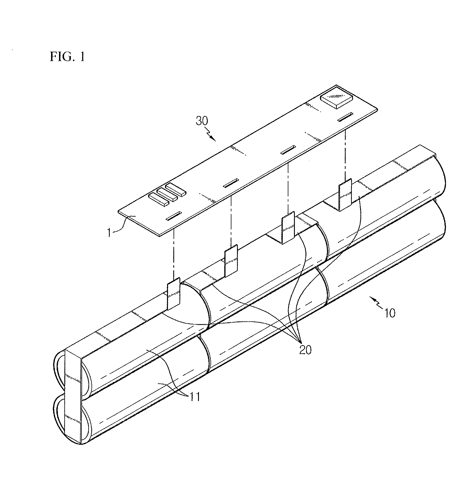
In addition, in the soldering or welding process for the core pack 10 and the protection circuit module 30, a short circuit may occur at the connection portion due to vibrations of the battery pack or an external impact, and an electric or thermal damage may be applied to the interface with the metal plate 20, which may become factors that threat the safety of the battery and increase the inferiority of products.
If not, a great voltage is abruptly applied from the core pack 10 to the protection circuit module 30, which may damage the internal circuit of the protection circuit module 30 and cause malfunction.
In particular, when there is a defect with a part of the unit cells or the protection circuit module 30 during the production process or in use, there is a disadvantage in that all components of the battery pack must be discarded.

Method used


Image

  • Connecting structure for secondary battery and battery pack including the same
  • Connecting structure for secondary battery and battery pack including the same
  • Connecting structure for secondary battery and battery pack including the same

Examples


first embodiment

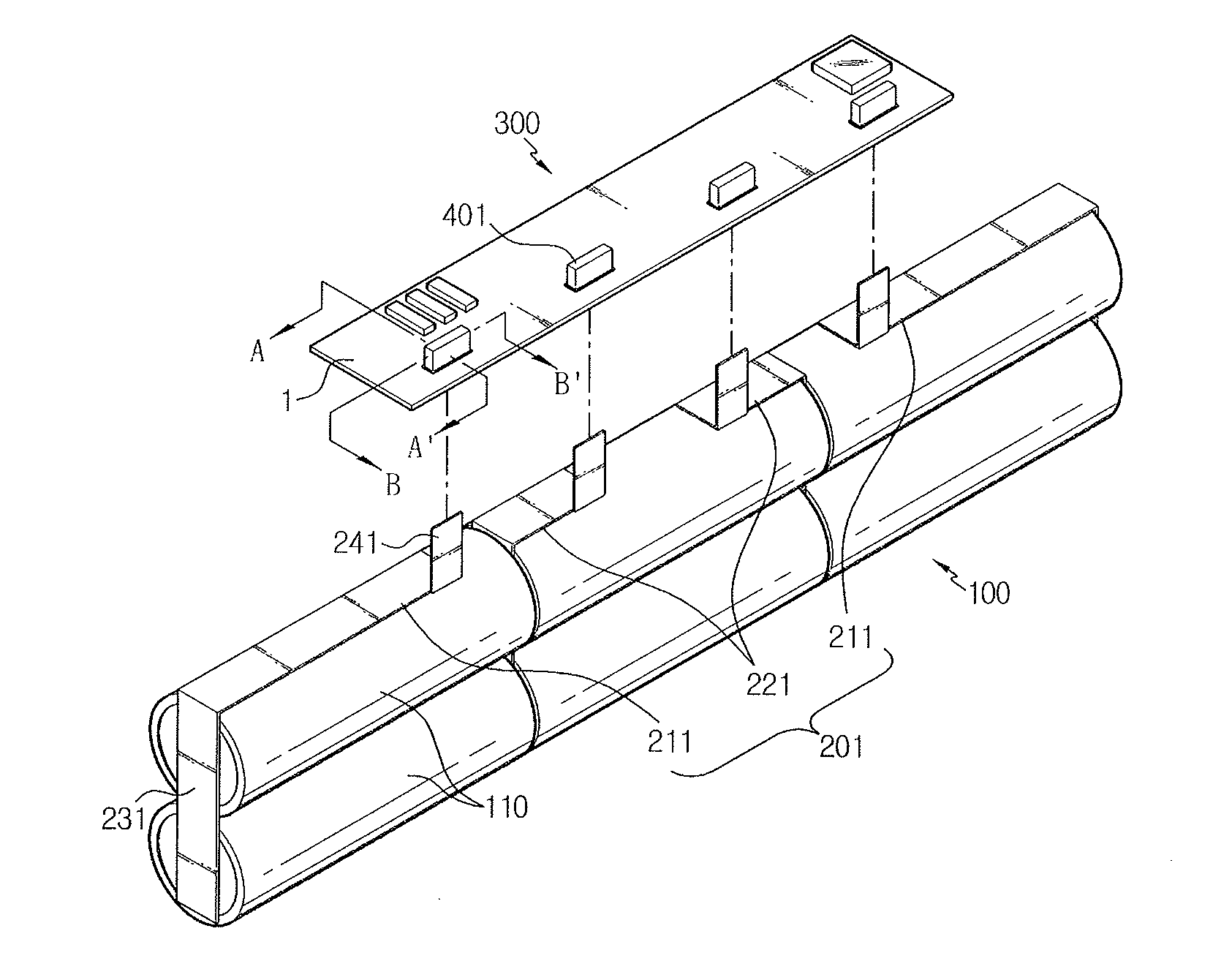
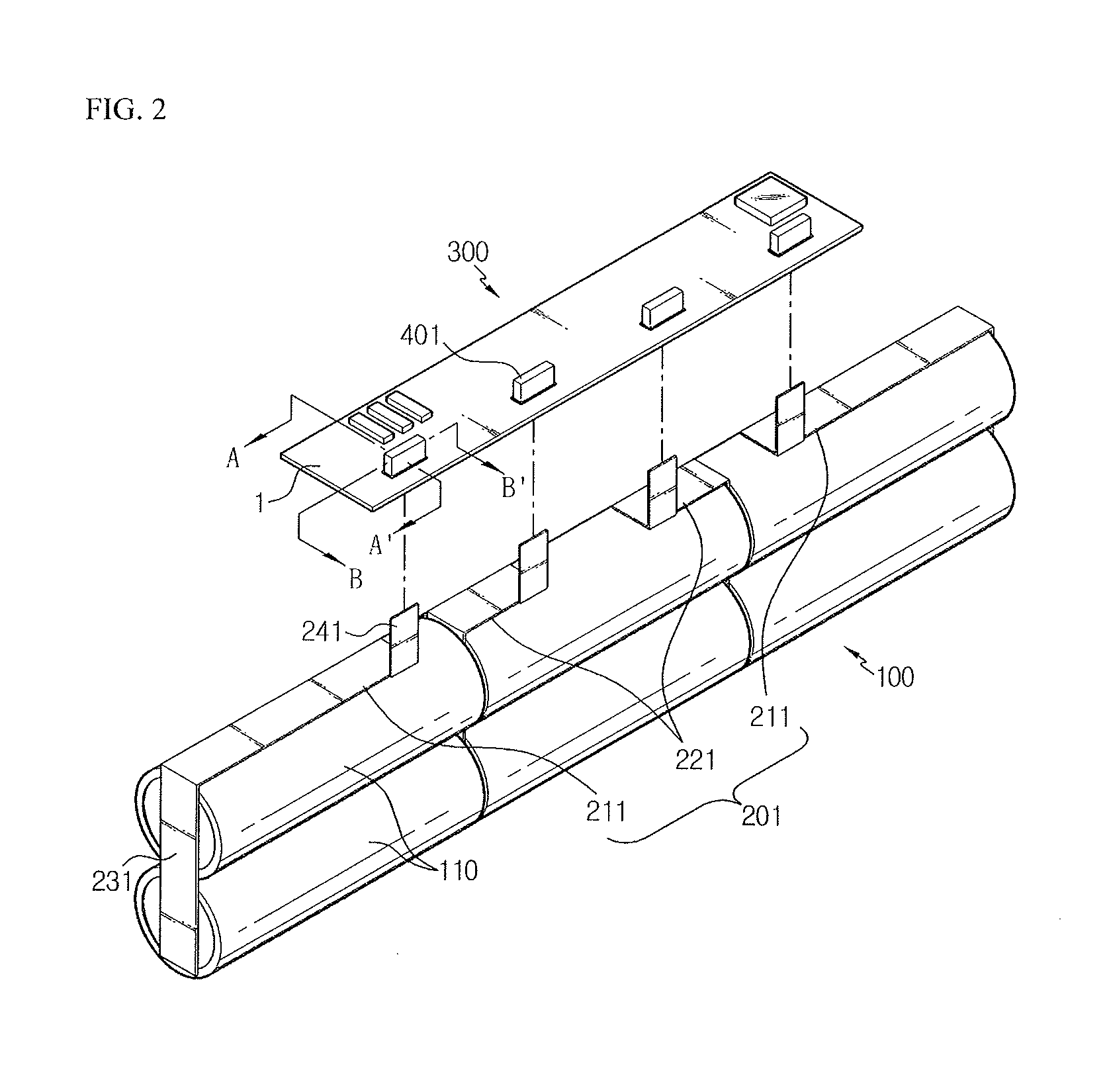
[0045]Referring to FIG. 2, a battery pack according to the present disclosure includes a core pack 100 where six unit cells 110 are arranged in a 2P (parallel)-3S (series) manner, and a soft pack where a protection circuit module 300 made of a PCB substrate 1 is electrically connected by means of four metal plates 201. Meanwhile, though not shown in FIG. 2, the soft pack may be sealed in a pack case.

[0046]The core pack 100 may form a single bank by electrically connecting a pair of unit cells 110 in parallel, and three banks may be connected in series. Here, each unit cell 110 may be a cylindrical or rectangular battery, but the cylindrical battery is preferred. Meanwhile, even though FIG. 2 depicts that the unit cells 110 of the core pack 100 are arranged in a 2P-3S manner, the present disclosure is not limited thereto and various structures such as 1P-2S, 1P-3S, 2P-2S, 2P-4S or the like may be applied, as obvious to those skilled in the art.

[0047]The metal plate 201 is used for el...

second embodiment

[0062]Hereinafter, in a battery pack according to the present disclosure, the connecting structure for a secondary battery for electrically connecting the core pack 100 and the protection circuit module 300 by means of the metal plates 202 will be described with reference to FIGS. 6 to 9.

[0063]As shown in FIGS. 6 to 9, the connecting structure for a secondary battery according to the second embodiment of the present disclosure is configured to include a coupling unit 262a or a screw coupling unit 262b provided at the circuit connecting unit 242 of the metal plate 202, and circuit terminal units 402a, 402b located at the PCB substrate 1 of the protection circuit module 300, and this structure gives electric connection by a physical connection method which allows selection connection or separation of the coupling unit 262a or the screw coupling unit 262b of the circuit connecting unit 242 and the circuit terminal units 402a, 402b.

[0064]The circuit terminal units 402a, 402b are insert...


PUM


Abstract

Disclosed is a connecting structure for a secondary battery and a secondary battery pack including the same. The connecting structure for a secondary battery electrically connects a core pack where two or more unit cells are electrically connected and a protection circuit module made of the unit cells of the core pack and a PCB substrate. The connecting structure includes a metal plate having an electrode connecting unit connected to an electrode of each unit cell of the core pack and a circuit connecting unit connected to the protection circuit module, and a circuit terminal unit electrically connected to the circuit connecting unit by being located in a connection hole formed in the PCB substrate of the protection circuit module so that the upper and lower portions of the PCB substrate communicate with each other, wherein the circuit connecting unit is electrically connected to the circuit terminal unit by means of a physical connection method which allows selective connection and separation.

Description

CROSS-REFERENCE TO RELATED APPLICATION[0001]The present application is a continuation of International Application No. PCT / KR2012 / 004549 filed on Jun. 8, 2012, which claims priority to Korean Patent Application No. 10-2011-0056289 filed in the Republic of Korea on Jun. 10, 2011, the disclosures of which are incorporated herein by reference.BACKGROUND OF THE DISCLOSURE[0002]1. Field of the Disclosure[0003]The present disclosure relates to a connecting structure for a secondary battery, and more particularly, to a connecting structure for a secondary battery, which connects the secondary battery to a protection circuit module, and a secondary battery pack including the same.[0004]2. Description of the Related Art[0005]Along with the technical development and increased demands of mobile devices, secondary batteries are used more and more as an energy source. Among them, lithium (ion / polymer) secondary batteries with high energy density, high operation voltage and excellent preservation...

Claims


Application Information

Patent Timeline
IPC IPC(8): H01M2/22H01M50/50H01M50/503H01M50/517H01M50/519H01M50/522H01M50/528H01M50/548H01M50/574
CPCH01M2/22H01M10/425H01M6/44H01M50/213H01M50/50H01M50/548H01M50/517H01M50/574H01M50/503H01M50/519H01M50/522H01R11/288Y02E60/10H01M50/528H01M10/02H01M50/531
Inventor SUNG, JONG-GYULEE, JAE-CHAN
Owner LG ENERGY SOLUTION LTD
Learn More