Ivc filter catheter with imaging modality

a filter catheter and imaging modality technology, applied in the field of vascular filters, can solve the problems of extending the time period, affecting the accuracy of catheterization, so as to facilitate intravascular imaging, improve the condition of the filter member, and target specific and accurately.

Active Publication Date: 2014-01-02
BIO2MEDICAL
View PDF4 Cites 7 Cited by
  • Summary
  • Abstract
  • Description
  • Claims
  • Application Information

AI Technical Summary

Benefits of technology

[0018]Each of the foregoing embodiments of the present invention may further be adapted for use with an imaging modality to facilitate intravascular imaging beyond or within the region of the filter member. In this manner, as opposed to the prior art, the condition of the filter member may be visualized from within the filter member, rather than via a traditional external imaging modality such as fluoroscopy, venography, or ultrasound. Additionally, in some embodiments, the imaging modality may pass entirely through the distal tip of the multi-lumen catheter, and enable an operator to use the intravascular imaging modality to visualize the origins of the renal veins. This could allow the operator to place the catheter without use of external imaging (i.e. fluoroscopy, trans-abdominal duplex ultrasound, CT, etc.).
[0019]Generally, intravascular imaging systems utilize a sheath through which a signal is transmitted and received. In the present invention, the multi-lumen catheter with associated filter member may serve as the sheath for introduction of an intravascular imaging system, permitting improved imaging of the condition of the filter member while in use. In particular, the use of an intravascular imaging system with the multi-lumen catheter with associated filter member will permit a medical professional to monitor the condition of the filter member, and utilize appropriate techniques to lyse a collected thrombus. Because of the improved imaging, the lysing techniques may be more specifically and accurately targeted, as compared to lysing techniques applied without the benefit of imaging the condition of the filter member. In other, alternative, embodiments, the intravascular imaging system may also enable a medical professional to visualize the filter catheter for placement within a patient.
[0021]In one embodiment, the imaging probe may be disposed within a portion of the central lumen bounded by the filter member. Thus, the imaging probe may be operated to help a user detect the presence of a thrombus captured by the filter member. Further, the imaging probe may also help detect the size and / or position of a captured thrombus. The imaging probe may be rotated and / or translated within the lumen, so as to permit imaging of the entire filter member. Alternatively, the imaging probe may be adapted to permit 360 degree imaging through the wall of the catheter lumen without requiring rotation. In a further embodiment, the imaging probe may be adapted to permit imaging of the length of the filter member without distal or proximal translation. Preferably, the imaging probe is operable to image the filter member in an expanded state.
[0024]In order to monitor the condition of the filter member, the imaging probe may transmit and receive an imaging signal through a wall of the lumen. The imaging signal may depend upon the particular imaging system utilized, and generally comprises a transmitted signal, wave, energy, or the like that is emitted from the imaging probe in order to image or visualize the filter member. In one embodiment, the relevant portion of the lumen is a section of the catheter body bounded by the proximal and distal ends of the filter member. The dimensions and / or material of any or all of the catheter body may be selected to maximize imaging signal transmission and / or imaging signal clarity.
[0025]Alternatively, in some embodiments the filter may be attached to an end of a single or a multi-lumen catheter. In these embodiments, the region bounded by the proximal and distal ends of the filter is open and free of imaging obstruction.

Problems solved by technology

Despite the efficacy of anticoagulant therapy in the management of VTE, there are certain situations and conditions in which the benefits of anticoagulation are outweighed by the risks of instituting such a therapy.
Currently these devices are not approved for use in the United States.
The time limit of retrievability is in part dependant on the rate of endothelialization of the device, which typically occurs within 2 weeks.
However, differences in design may extend the time period in which the filter may be safely retrieved.
However, misplacement of an SVC filter is theoretically more likely than with an IVC filter because of the relatively short target area for deployment.
Vena cava filter placement frequently occurs concomitantly with central access line placement or in critically ill patients that already have a central access line in place.
Heretofore, however, there have been no devices which combine the function of a central access catheter and a removable vena cava filter.

Method used


Image

  • Ivc filter catheter with imaging modality
  • Ivc filter catheter with imaging modality
  • Ivc filter catheter with imaging modality

Examples


first embodiment

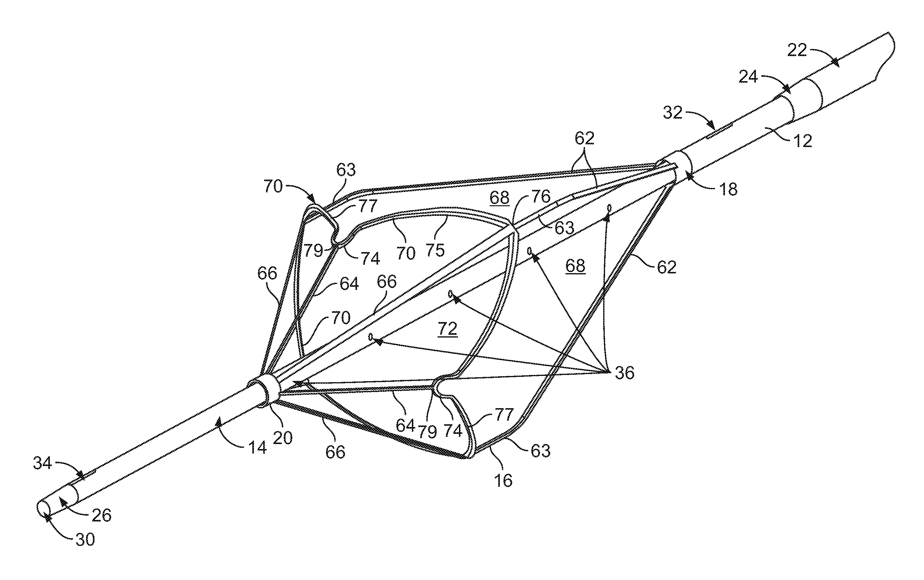
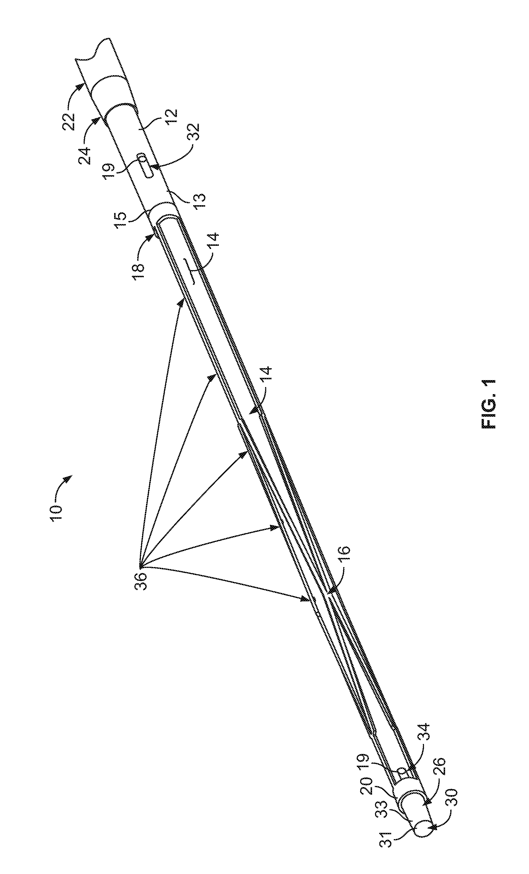
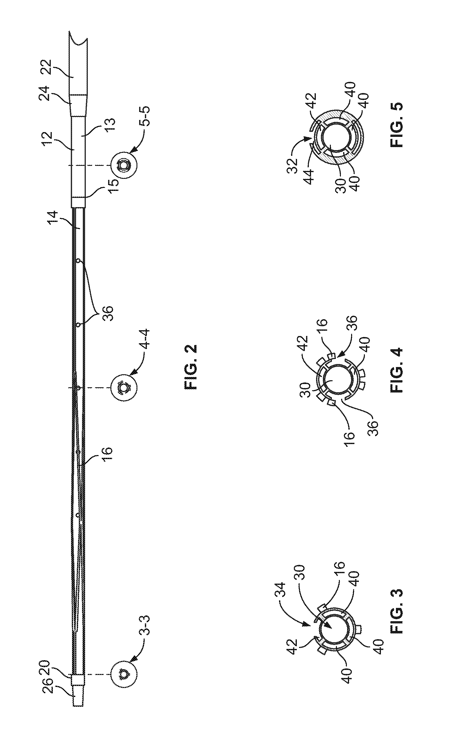
[0058]In the accompanying Figures like structural or functional elements are designated by like reference numerals, e.g., 16, 116, 216, 316, 416 represent similar structural or functional elements across different embodiments of the invention. With particular reference to FIGS. 1-5, according to the invention, there is disclosed a central venous access filter (“CVAF”) 10 that is composed generally of a multi-lumen central venous access catheter body 12 having a proximal port 32 associated with a first lumen 44 and a distal port 34 associated with a second lumen 42, a filter member 16, having a first end 18 and a second end 20, is positioned generally intermediate the distal port 34 and the proximal port 32 and is generally concentric relative to the catheter body 12. An outer sheath 22 is concentrically disposed over the catheter body 12 such that relative movement of the catheter body 12 and the outer sheath 22 either exposes the filter member 16 or captures the filter member 16 wi...

second embodiment

[0067]FIGS. 6-11 illustrate the CVAF 50. Unlike CVAF 10, CVAF 50 does not include the central guidewire lumen 30 of CVAF 10. Rather, while the general construct of CVAF 50 is similar to that of CVAF 10, a different configuration of the inner lumens is employed.

[0068]CVAF 50, like CVAF 10, consists generally of a multi-lumen central venous access catheter body 12 having a proximal port 32 associated with a first lumen 54 and a distal port 34 associated with a second lumen 58, a filter member 16, having a fixed first end 18 and a moveable second end 20, is positioned generally intermediate the distal port 34 and the proximal port 32 and is generally concentric relative to the catheter body 12. Use of the term “generally intermediate” is intended to mean that at least a substantial portion of the filter member 16 resides intermediate the distal port 34 and the proximal port 32. Thus, the filter member 16 may partially overlay either or both of the proximal port 32 or the distal port 34...


PUM


Abstract

A combined multi-lumen central access catheter and an embolic filter, further comprising an imaging modality to facilitate intravascular imaging of the filter.

Description

CROSS-REFERENCE TO RELATED APPLICATIONS[0001]This application is a continuation of U.S. patent application Ser. No. 13 / 735,810, filed Jan. 7, 2013, which is continuation-in-part of co-pending U.S. patent application Ser. No. 12 / 684,839 filed Jan. 8, 2010, which is a continuation-in-part of co-pending U.S. patent application Ser. No. 11 / 849,225 filed Aug. 31, 2007, all of which are hereby incorporated by reference in their entirety and from which priority is hereby claimed.[0002]This application is a continuation-in-part of commonly owned and co-pending U.S. Provisional Patent Application Ser. No. 61 / 668,308, filed Jul. 5, 2012, which is hereby incorporated by reference in its entirety.BACKGROUND OF THE INVENTION[0003]The present invention pertains generally to the field of vascular filters for capturing embolic material in the blood flow.[0004]The accepted standard of care for patients with venous thromboembolism (VTE) is anticoagulant therapy. Inferior vena cava (IVC) filters are r...

Claims


Application Information

Patent Timeline
Patent Type & Authority Applications(United States)
IPC IPC(8): A61F2/01A61B5/00A61M25/01A61B8/12
CPCA61F2/013A61B8/12A61B5/0066A61B5/0084A61M25/01A61M25/0029A61F2002/016A61F2002/018A61M2025/0002A61M2025/0003A61M2025/0036A61M2025/004A61M2205/3523A61F2230/008A61F2230/0093A61B5/6853A61B5/6859A61B5/0013A61B5/02007A61B5/0215A61B5/026A61B8/445A61B8/4461A61B2090/3966A61F2/011A61B17/00234A61B1/0125A61B1/00133A61B2017/00296
Inventor ANGEL, LUIS F.STEINMETZ, JEFFREY N.SIMS, DANIEL D.
Owner BIO2MEDICAL
Why Eureka
Try Eureka