Device for Controlling a Coffee Maker

a coffee maker and control device technology, applied in the field of electric coffee maker control, to achieve the effect of reducing cost and facilitating replacemen

Active Publication Date: 2014-01-02
HOFFMAN RONALD J
View PDF48 Cites 19 Cited by
  • Summary
  • Abstract
  • Description
  • Claims
  • Application Information

AI Technical Summary

Benefits of technology

[0007]The problem to be addressed is how to offer all of the advanced features discussed in the '998 patent without using a triac or a thermal sensor. Since standard coffee makers use a bi-metal thermostat to regulate the temperature, a method to control the coffee maker by monitoring the ON-OFF condition of the thermostat is required. Additionally, there are two ways to monitor the thermostat condition. The first way is by connecting a wire to a point between the thermostat and the heater load and detecting a voltage across the load when the thermostat is closed. When the thermostat is open, there is no voltage across the heater load. The first way requires an additional wire to monitor the thermostat. A second way for monitoring the thermostat is by sensing the current drawn through the heater load when the thermostat is closed. This method offers two distinct advantages. One, the current sensing approach does not require an additional wire in order to monitor the thermostat condition. Second, it allows the current being passed to the coffee maker to be monitored externally. This allows the coffee maker control unit to be separate from the coffee maker. Therefore, it becomes a universal method to monitor and control any brand, model or size of automatic electric coffee maker. Now, any simple ON-OFF switch-type a coffee maker can be controlled to provide advanced features. The coffee maker controller “(CMC)” with a CMC receptacle could now be plugged into an AC receptacle and the coffee maker plugged into the CMC receptacle. A further advantage to this approach is that if the coffee maker should fail, it can be easily be replaced with a dower cost switch type electric coffee maker and just plugged into the CMC. No reprogramming is required, and the cost savings are substantial.
[0020]A still further object is to provide a programmable WARM temperature controller to control the temperature of the coffee and protect the fresh taste of the coffee.

Problems solved by technology

The problem to be addressed is how to offer all of the advanced features discussed in the '998 patent without using a triac or a thermal sensor.

Method used


Image

  • Device for Controlling a Coffee Maker
  • Device for Controlling a Coffee Maker
  • Device for Controlling a Coffee Maker

Examples


Embodiment Construction

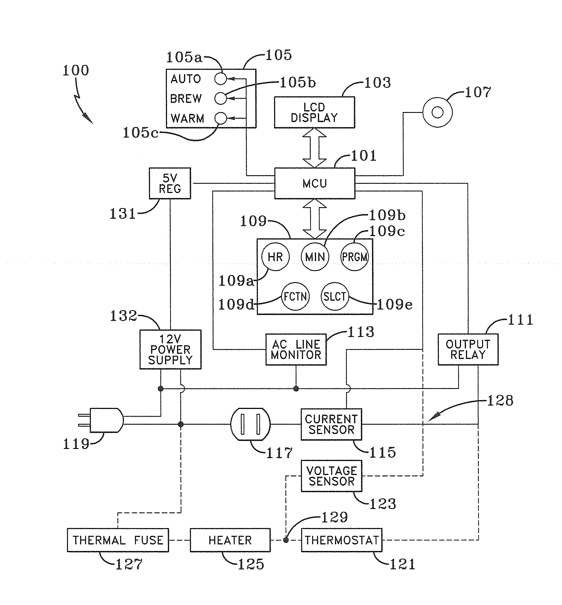
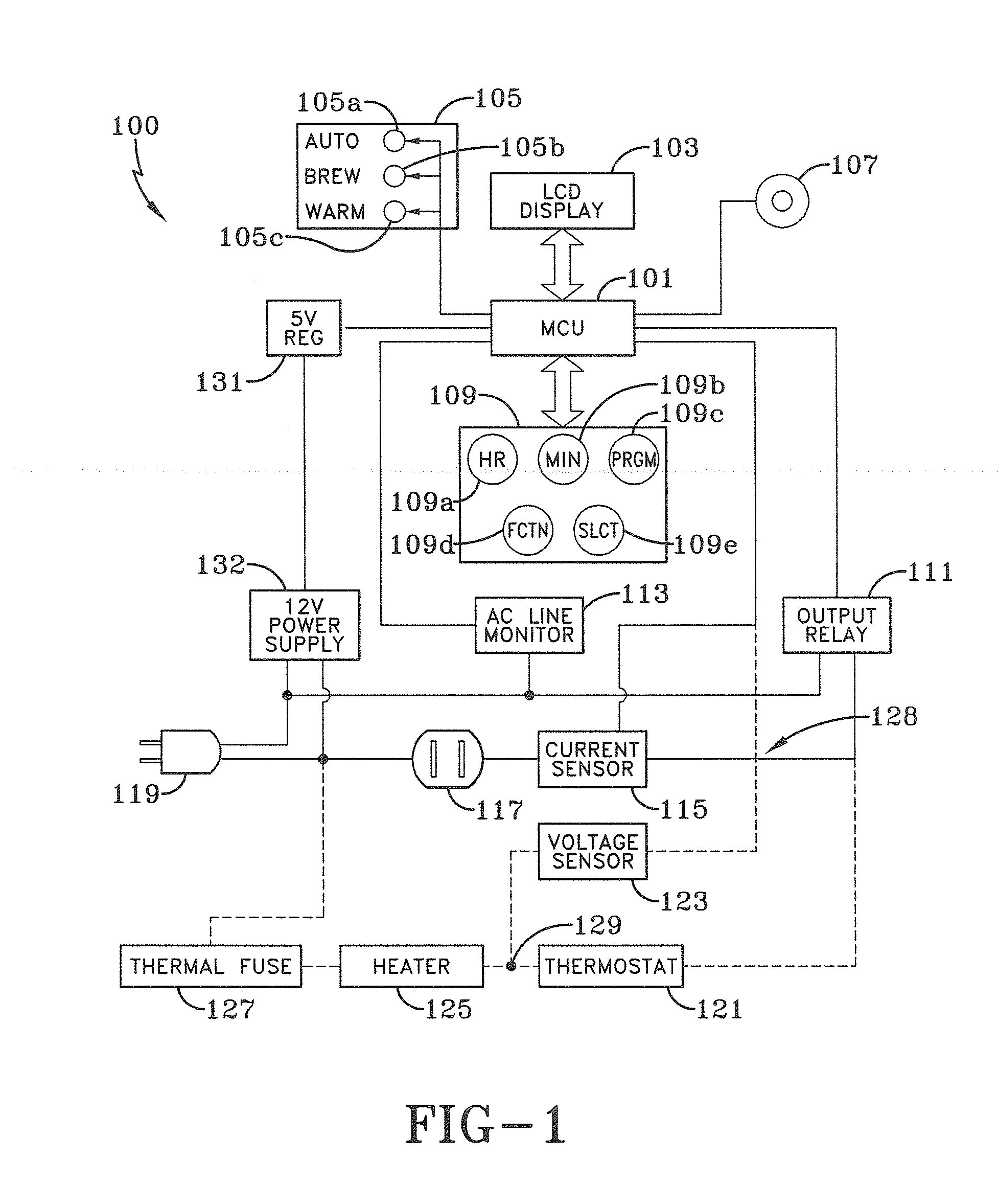
[0036]An aspect of the invention relates to monitoring the condition of a thermostat 421 shown in FIG. 4E via either a voltage sensing resistor 423, or a current sensing device as discussed below. The voltage sensing resistor 423 is the simplest electrical device but requires a coffee maker controller to be installed in the coffee maker. A coffee maker controller diagram is shown schematically in FIG. 1 (and discussed below) with the dotted lines showing an alternate configuration to a thermostat 121, a voltage sensor 123, an electric heater 125 and a thermal fuse 127. The current sensing device allows for independent (stand alone) control of a coffee maker. The current sensing device provides control to any size or brand of coffee maker with an ON-OFF switch. It also requires that only the defective coffee maker with a switch has to be replaced, rather than requiring buying the coffee maker controller with its electronics over and over.

[0037]Another aspect of the invention is the p...


PUM


Abstract

A control module suitable for controlling a manual switch type automatic drip coffeemaker (ADC) enabling the addition of fully automatic brewing start, programmable brewing strengths, programmable heater levels for keeping the coffee warm after the brewing cycle is complete, programmable shut-off time periods, automatic cleaning detector, automatic self cleaning cycle with automatic shut-off, and programmable twelve hour AM / PM or twenty-four hour time format. The control module contains a micro-controller, application specific firmware, a keypad, a liquid crystal display, a control relay, a current or a voltage sensor, indicator LED's, a piezo audible alarm, and power supply components.

Description

CROSS REFERENCE TO RELATED APPLICATION[0001]This application claims priority of U.S. Provisional Application No. 61 / 658,990, filed Jun. 13, 2012, under Title 35, United States Code, Section 119(e), which is incorporated by reference herein in its entirety.BACKGROUND OF THE INVENTION[0002]1. Field of the Invention[0003]This invention relates to controls for electric coffee makers, and in particular to a control module for manual switch-type automatic drip coffee machines.[0004]2. Description of the Prior Art[0005]In 1993, U.S. Pat. No. 5,183,998 (Hoffman et al., “the '998 patent”) was issued describing an automatic electric coffee maker or the like having user selectable AUTO, BREW, WARM or OFF states. The control used a triac to provide full power to brew the coffee, and reduced power which could be user adjusted to set the WARM temperature level. A temperature sensor could determine if the machine should be cleaned and to determine if the BREW state was complete and automatically c...

Claims


Application Information

Patent Timeline
Patent Type & Authority Applications(United States)
IPC IPC(8): G05B19/042
CPCG05B19/042A47J31/52A47J31/5253
Inventor HOFFMAN, RONALD J.
Owner HOFFMAN RONALD J
Why Eureka
Try Eureka