Filter device for gas flow loaded with aerosoles and/or gaseous iodine

a filter device and gas flow technology, applied in the direction of greenhouse gas reduction, separation processes, nuclear elements, etc., can solve the problems of large amount of steam and non-condensable gases generated by meltdown, pressure buildup in containment vessels, etc., to increase the surface area of the filter device, reduce the effect of thermal energy loss

Inactive Publication Date: 2014-01-09
YIT GERMANY
View PDF0 Cites 10 Cited by
  • Summary
  • Abstract
  • Description
  • Claims
  • Application Information

AI Technical Summary

Benefits of technology

[0031]In another advantageous embodiment, an outer enveloping surface of the at least one tubular element is coated black. This increases an absorption capability of the tubular elements relative to heat radiation which has the effect that the tubular elements absorb more heat radiation which is subsequently dissipated. This way, tubular elements of this type are particularly well-suited to remove as much thermal energy as possible from the filter device.
[0032]In order to further increase the surface of the filter device, it is particularly advantageous when the at least one tubular element has ribs or fold-overs extending over at least part of its length from an inner enveloping surface into the inner cavity of the tubular element.
[0033]According to an advantageous embodiment of the filter device according to the invention, support elements are arranged in flow direction of the gas downstream of the filter element, wherein the support elements are formed by the tube elements. Thus, the tube elements perform a double function which on the one hand side serves to improve the cooling of the filter device and on the other hand side serves to counteract a bending of the filter element that is caused by the incoming gas flow. The

Problems solved by technology

A core meltdown generates large amounts of steam and non-condensable gases through evaporation of the cooling water from the primary cooling cycle of the reactor and through des

Method used


Image

  • Filter device for gas flow loaded with aerosoles and/or gaseous iodine
  • Filter device for gas flow loaded with aerosoles and/or gaseous iodine
  • Filter device for gas flow loaded with aerosoles and/or gaseous iodine

Examples


Embodiment Construction

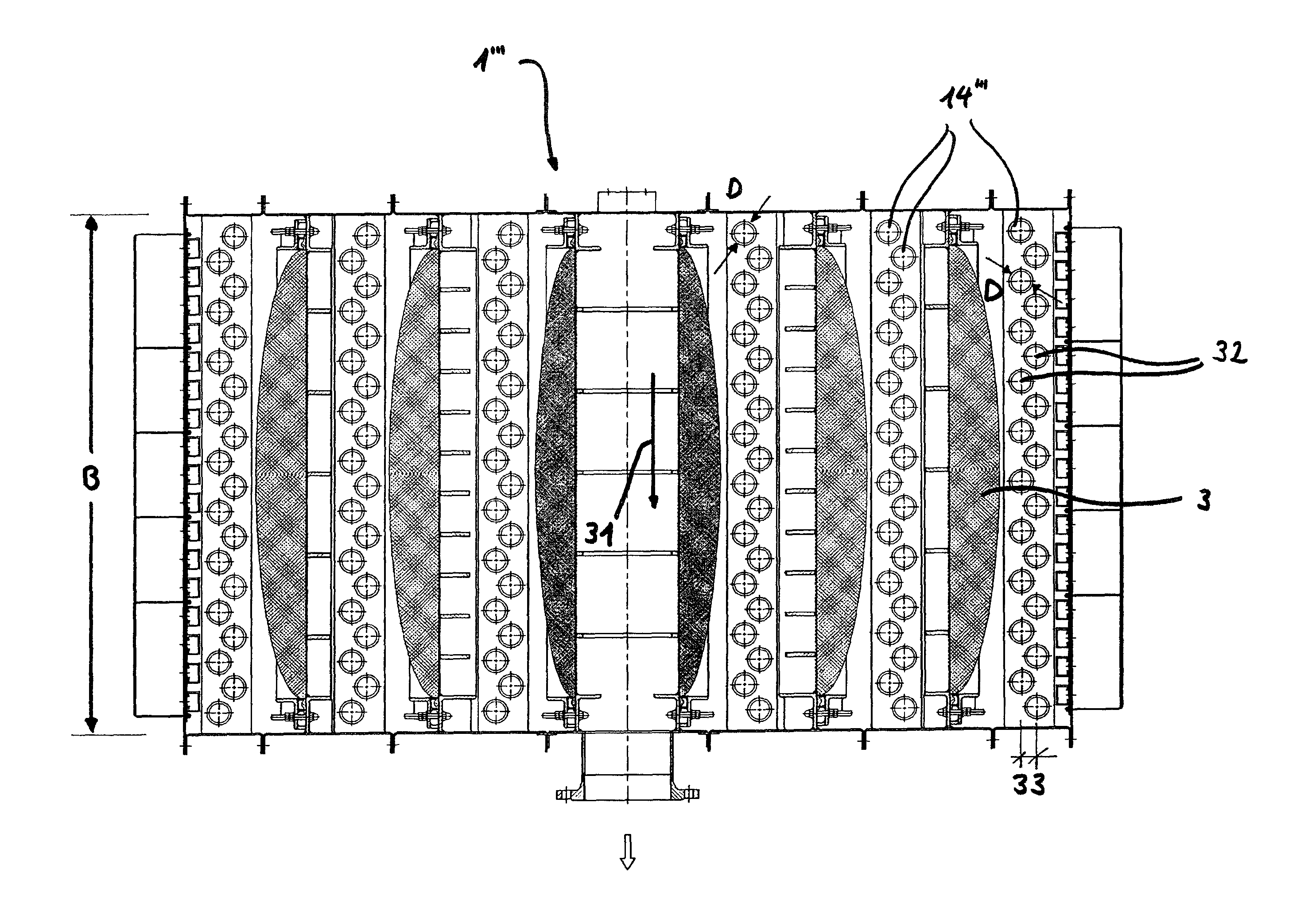
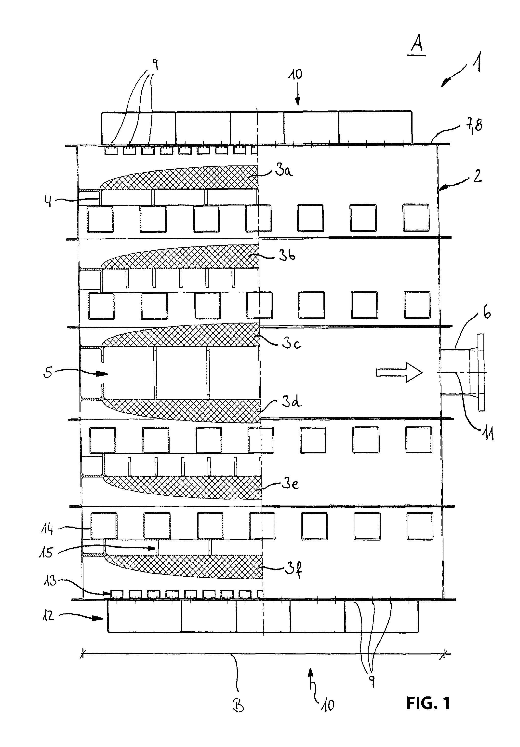
[0044]FIG. 1 illustrates a filter device 1 according to the invention in one half as a top view and in the other half as a horizontal sectional view. The filter device 1 includes an approximately cuboid housing 2 with a rectangular cross-section in which six filter elements 3a, 3b, 3c, 3d, 3e, 3f with a filter material that is formed by metal fleeces are arranged in parallel and at a distance from one another, wherein the filter elements are supported in a sealing manner respectively circumferentially at circumferentially attached consoles 4 of the housing 2 and thus respectively close the cross-section of the housing 2. The particular support of the filter elements 3 at the consoles 4 can be provided in a conventional manner and is therefore not illustrated in the figures for reasons of clarity. The filter elements 3 have a sickle shaped cross-section so that they have a small thickness along the consoles 4, whereas they are configured thicker in the center.

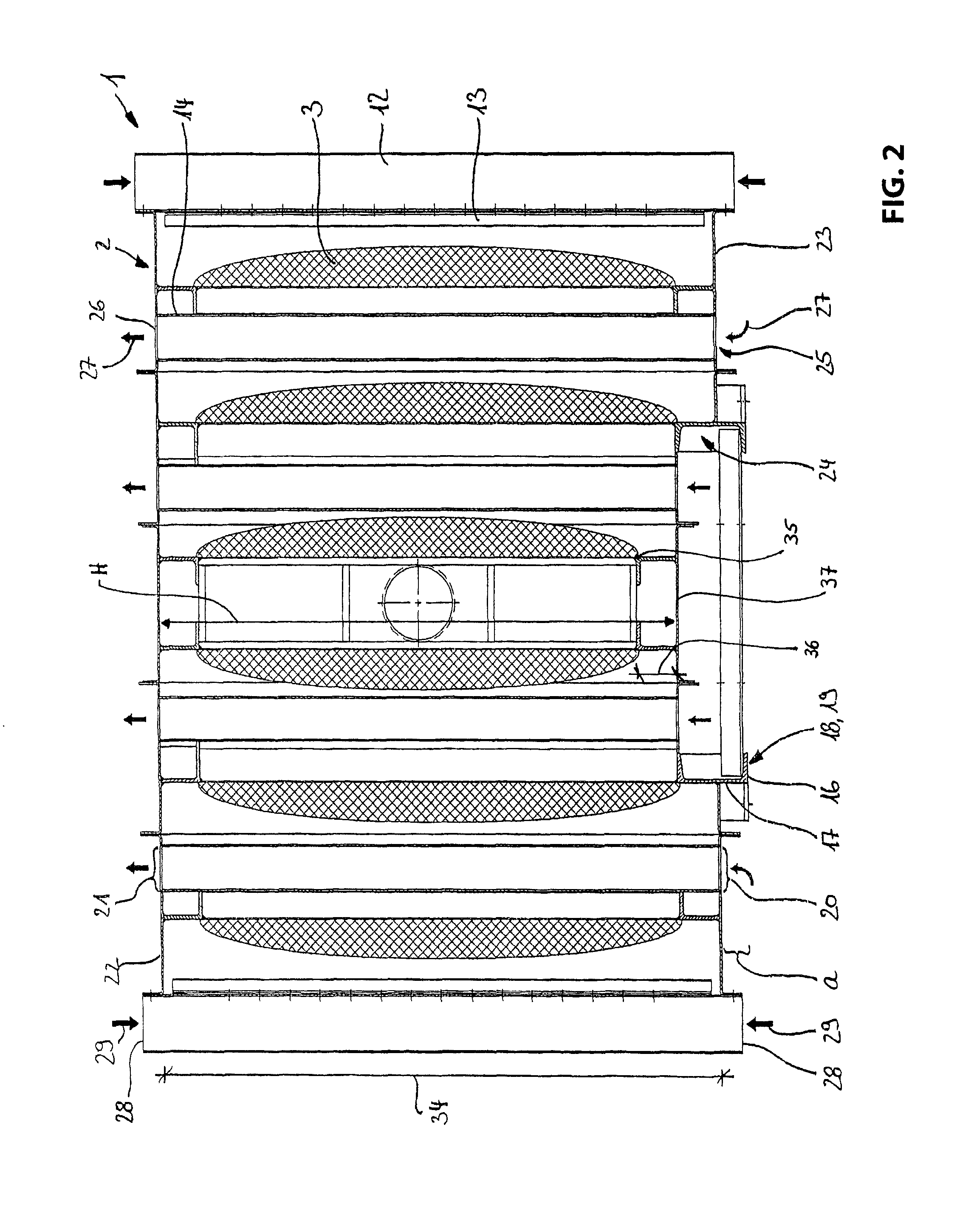
[0045]In the center of t...


PUM

PropertyMeasurementUnit
Lengthaaaaaaaaaa
Flow rateaaaaaaaaaa
Diameteraaaaaaaaaa

Abstract

The invention relates to a filter device for filtering a gas flow that is loaded with aerosols and/or gaseous radioactive iodine including a housing that is closed fluid tight, including at least one raw gas inlet, a clean gas outlet, at least one filter element including a filter medium, the filter element is arranged in the housing so that a gas flow to be filtered moves from the at least one raw gas inlet to the clean gas outlet only through the filter element, at least one tubular element penetrating the housing from a first pass-through cross-section to a second pass through cross-section which is arranged in vertical direction above the first pass through cross-section, so that an entire inner cavity of the tubular element is exclusively in contact with an ambient fluid surrounding the filter device.

Description

RELATED APPLICATIONS[0001]This application claims priority from and incorporates by reference German patent application 10 2011 056 889.1, filed on Dec. 22, 2011.FIELD OF THE INVENTION[0002]The invention relates to a filter device for filtering a gas flow that is loaded with radioactive aerosols and / or gaseous radioactive iodine including a housing that is closed fluid tight including at least one raw gas inlet, a clean gas outlet and at least one filter element including a filter medium which filter element is arranged in the housing so that the gas flow to be filtered moves from the at least one raw gas inlet exclusively through the filter element to the clean gas outlet.BACKGROUND OF THE INVENTION[0003]Filter devices of the type recited supra are well known and are used for numerous applications in the field of nuclear technology, wherein the filter devices have to comply with the respective requirements of these applications.[0004]A core meltdown generates large amounts of steam...

Claims


Application Information

Patent Timeline
IPC IPC(8): B01D46/00
CPCB01D46/00G21C9/00G21C11/022G21C13/10G21C19/303G21F9/02B01D53/0407B01D2253/108B01D2257/20B01D2257/2068Y02E30/30B01D46/02G21F9/00
Inventor MARTINSTEG, HANS
Owner YIT GERMANY
Why Eureka
Try Eureka