
Integrated circuit and method for fabricating the same having a replacement gate structure

a technology of integrated circuits and gate structures, which is applied in the direction of transistors, electrical devices, semiconductor devices, etc., can solve the problems of adversely affecting transistor performance, micro-miniaturization engendering a dramatic increase in transistor engineering complexity, adversely affecting leakage current, etc., and achieves low resistance

Inactive Publication Date: 2014-01-09
ALSEPHINA INNOVATIONS INC
View PDF8 Cites 91 Cited by
  • Summary
  • Abstract
  • Description
  • Claims
  • Application Information

AI Technical Summary

Benefits of technology

This patent text describes methods and structures for fabricating integrated circuits with multiple tranches and layers of material. The technical effects include improved performance and reliability of the integrated circuits through the use of workfunction materials and barrier materials, as well as the optimization of the layout and deposition of the layers to achieve better performance and reliability. The patent also describes a method for filling unfilled trenches with a low-resistance fill material and optimizing the material composition to achieve better performance and reliability. Additionally, the patent describes the use of a sacrifice fill material and a gate fill material to further improve the performance and reliability of the integrated circuits.

Problems solved by technology

Micro-miniaturization has engendered a dramatic increase in transistor engineering complexity, such as the inclusion of lightly doped drain structures, multiple implants for source / drain regions, silicidation of gates and source / drains, and multiple sidewall spacers, for example.
Typically, the structural and doping parameters tending to provide a desired increase in drive current adversely impact leakage current.
However, simply replacing polysilicon gate electrodes with metal gate electrodes may engender issues in forming the metal gate electrode prior to high temperature annealing to activate the source / drain implants, as at a temperature in excess of 900° C. Such fabrication techniques may degrade the metal gate electrode or cause interaction with the gate dielectric, thereby adversely impacting transistor performance.
Additional issues arise with lateral scaling, such as the formation of contacts.
This will cause high resistance issue for devices with small gate lengths, and will also cause problems in the SAC replacement gate metal recess, where the metal gate structures for long channel devices are significantly different from short channel devices.

Method used


Image

  • Integrated circuit and method for fabricating the same having a replacement gate structure
  • Integrated circuit and method for fabricating the same having a replacement gate structure
  • Integrated circuit and method for fabricating the same having a replacement gate structure

Examples


Embodiment Construction

[0014]The following detailed description is merely illustrative in nature and is not intended to limit the embodiments of the subject matter or the application and uses of such embodiments. As used herein, the word “exemplary” means “serving as an example, instance, or illustration.”Any implementation described herein as exemplary is not necessarily to be construed as preferred or advantageous over other implementations. Furthermore, there is no intention to be bound by any expressed or implied theory presented in the preceding technical field, background, brief summary or the following detailed description.

[0015]For the sake of brevity, conventional techniques related to semiconductor device fabrication may not be described in detail herein. Moreover, the various tasks and process steps described herein may be incorporated into a more comprehensive procedure or process having additional steps or functionality not described in detail herein. In particular, various steps in the manuf...


PUM

PropertyMeasurementUnit
temperatureaaaaaaaaaa
thicknessaaaaaaaaaa
workfunctionaaaaaaaaaa

Abstract

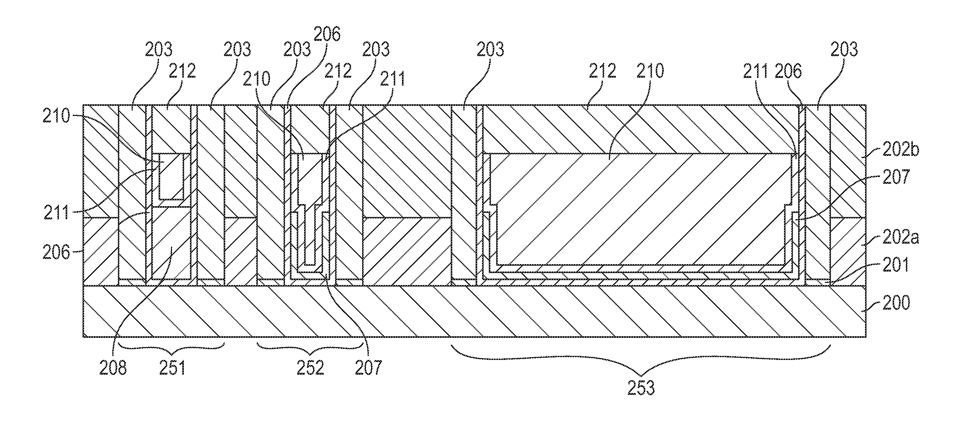
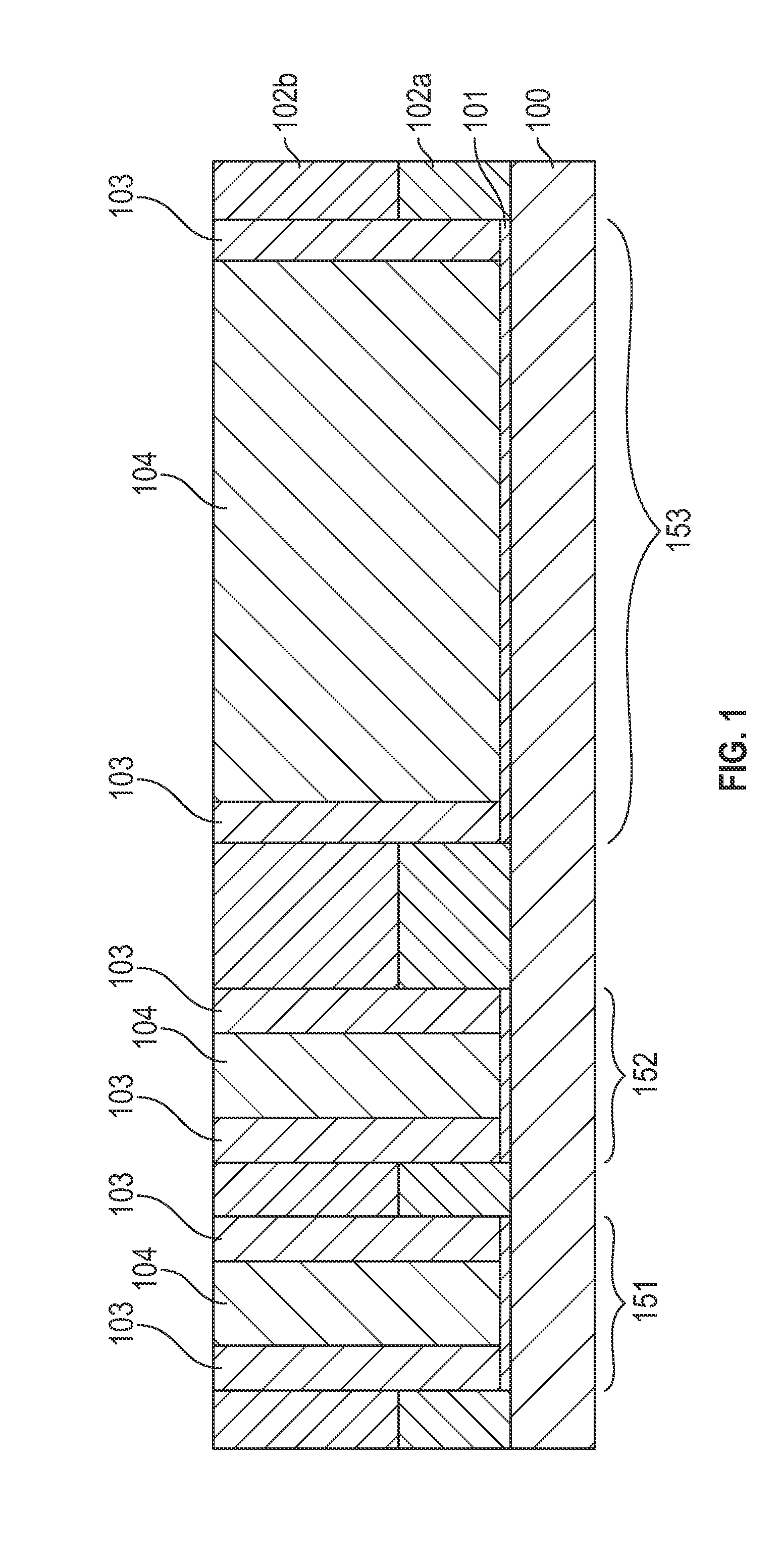
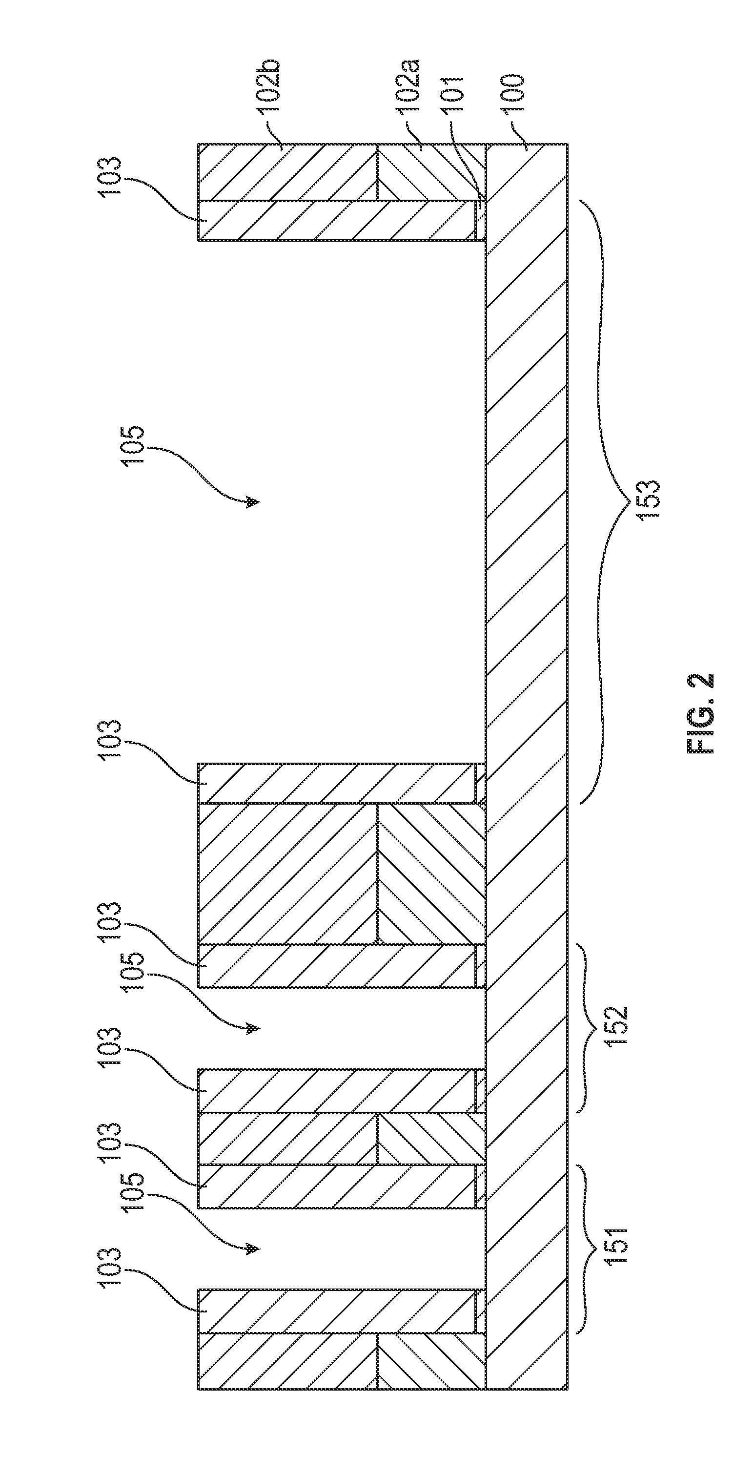
A method for fabricating an integrated circuit includes forming a first layer of a workfunction material in a first trench of a plurality of trench structures formed over a silicon substrate, the first trench having a first length and forming a second layer of a workfunction material in a second trench, the second trench having a second length that is longer than the first length. The method further includes depositing a low-resistance fill material onto the integrated circuit to fill any unfilled trenches with the low-resistance fill material and etching the low resistance fill material, the first layer, and the second layer to re-expose a portion of each trench of the plurality of trenches, while leaving a portion of each of the first layer, the second layer, and the low-resistance fill material in place. Still further, the method includes depositing a gate fill material into each re-exposed trench portion.

Description

TECHNICAL FIELD[0001]Embodiments of the subject matter described herein relate generally to integrated circuits and methods for fabricating integrated circuits. More particularly, the subject matter relates to integrated circuits and methods for fabricating integrated circuits having a replacement gate structure.BACKGROUND[0002]The integration of hundreds of millions of circuit elements, such as transistors, on a single integrated circuit necessitates further dramatic scaling down or micro-miniaturization of the physical dimensions of circuit elements, including interconnection structures. Micro-miniaturization has engendered a dramatic increase in transistor engineering complexity, such as the inclusion of lightly doped drain structures, multiple implants for source / drain regions, silicidation of gates and source / drains, and multiple sidewall spacers, for example.[0003]The drive for high performance requires high speed operation of microelectronic components requiring high drive cu...

Claims


Application Information

Patent Timeline
Patent Type & Authority Applications(United States)
IPC IPC(8): H01L27/092H01L21/3205
CPCH01L27/092H01L21/823456H01L21/823842H01L21/28088H01L29/4966H01L29/517H01L29/66545H01L27/0922H01L29/42364H01L29/4958
Inventor XIE, RUILONGBALASUBRAMANIAN, PRANATHARTHI HARAN
Owner ALSEPHINA INNOVATIONS INC
Learn More